


9 ENGLISH
FUNCTIONAL
DESCRIPTION
CAUTION:
Always be sure that the tool is
switched off and the battery cartridge is removed
before adjusting or checking function on the tool.
Installing or removing battery
cartridge
CAUTION:
Always switch off the tool before
installing or removing of the battery cartridge.
CAUTION:
Hold the tool and the battery car-
tridge firmly when installing or removing battery
cartridge.
Failure to hold the tool and the battery
cartridge firmly may cause them to slip off your hands
and result in damage to the tool and battery cartridge
and a personal injury.
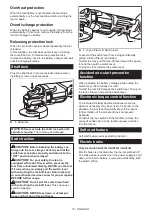
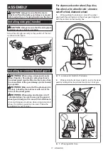
2
3
1
►
1.
Red indicator
2.
Button
3.
Battery cartridge
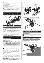
To remove the battery cartridge, slide it from the tool
while sliding the button on the front of the cartridge.
To install the battery cartridge, align the tongue on the
battery cartridge with the groove in the housing and slip
it into place. Insert it all the way until it locks in place
with a little click. If you can see the red indicator on the
upper side of the button, it is not locked completely.
CAUTION:
Always install the battery cartridge
fully until the red indicator cannot be seen.
If not,
it may accidentally fall out of the tool, causing injury to
you or someone around you.
CAUTION:
Do not install the battery cartridge
forcibly.
If the cartridge does not slide in easily, it is
not being inserted correctly.
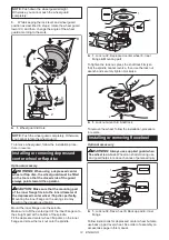
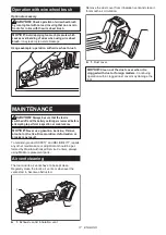
Indicating the remaining battery
capacity
Press the check button on the battery cartridge to indi-
cate the remaining battery capacity. The indicator lamps
light up for a few seconds.
1
2
►
1.
Indicator lamps
2.
Check button
Indicator lamps
Remaining
capacity
Lighted
Off
Blinking
75% to 100%
50% to 75%
25% to 50%
0% to 25%
Charge the
battery.
The battery
may have
malfunctioned.
NOTE:
Depending on the conditions of use and the
ambient temperature, the indication may differ slightly
from the actual capacity.
Tool / battery protection system
The tool is equipped with a tool/battery protection sys-
tem. This system automatically cuts off power to the
motor to extend tool and battery life. The tool will auto-
matically stop during operation if the tool or battery is
placed under one of the following conditions:
Overload protection
When the tool/battery is operated in a manner that
causes it to draw an abnormally high current, the tool
automatically stops without any indication. In this sit-
uation, turn the tool off and stop the application that
caused the tool to become overloaded. Then turn the
tool on to restart.
Summary of Contents for GA012G
Page 19: ...19 ...


