


7 ENGLISH
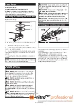
FUNCTIONAL
DESCRIPTION
CAUTION:
Always be sure that the tool is
switched off and unplugged before adjusting or
checking function on the tool.
CAUTION:
Return the slide switch to the “O
(OFF)” position in case of accidental unplugging,
blackout, or the power is cut unintentionally.
Otherwise the tool may start suddenly when the
power returns and it may result in personal injury.
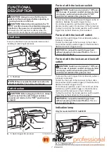
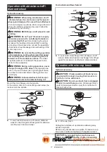
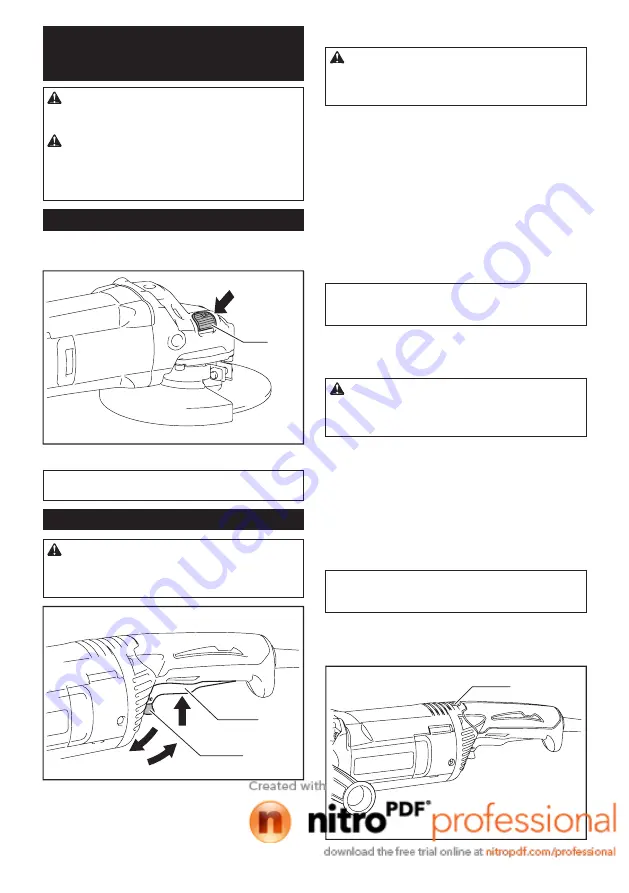
Shaft lock
Press the shaft lock to prevent spindle rotation when
installing or removing accessories.
1
►
1.
Shaft lock
NOTICE:
Never actuate the shaft lock when the
spindle is moving.
The tool may be damaged.
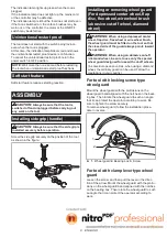
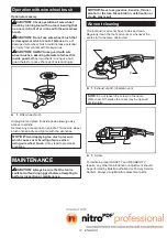
Switch action
CAUTION:
Before plugging in the tool, always
check to see that the switch trigger actuates
properly and returns to the "OFF" position when
released.
A
B
C
2
1
►
1.
Switch trigger
2.
Lock lever
For tool with the lock-on switch
CAUTION:
Switch can be locked in "ON" posi-
tion for ease of operator comfort during extended
use. Apply caution when locking tool in "ON"
position and maintain firm grasp on tool.
To start the tool, simply pull the switch trigger (in the B
direction). Release the switch trigger to stop.
For continuous operation, pull the switch trigger (in the B
direction) and then push in the lock lever (in the A direction).
To stop the tool from the locked position, pull the switch
trigger fully (in the B direction), then release it.
For tool with the lock-off switch
To prevent the switch trigger from accidentally pulled, a
lock lever is provided.
To start the tool, push in the lock lever (in the A direc
-
tion) and then pull the switch trigger (in the B direction).
Release the switch trigger to stop.
NOTICE:
Do not pull the switch trigger hard
without pressing in the lock-off button.
This can
cause switch breakage.
For tool with the lock-on and lock-off
switch
CAUTION:
Switch can be locked in "ON" posi-
tion for ease of operator comfort during extended
use. Apply caution when locking tool in "ON"
position and maintain firm grasp on tool.
To prevent the switch trigger from accidentally pulled, a
lock lever is provided.
To start the tool, push in the lock lever (in the A direc
-
tion) and then pull the switch trigger (in the B direction).
Release the switch trigger to stop.
For continuous operation, push in the lock lever (in the
A direction), pull the switch trigger (in the B direction)
and then pull the lock lever (in the C direction).
To stop the tool from the locked position, pull the switch
trigger fully (in the B direction), then release it.
NOTICE:
Do not pull the switch trigger hard
without pressing in the lock-off button.
This can
cause switch breakage.
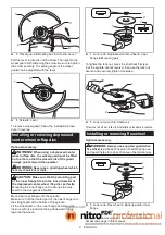
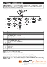
Indication lamp
Only for model GA7061R / GA9061R
1
►
1.
Indication lamp


