background image

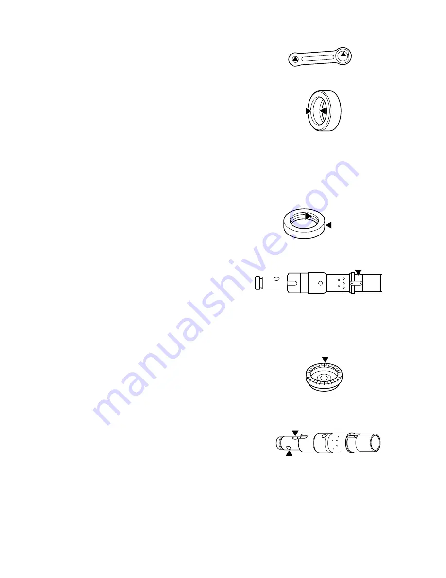
          Rod :

                               Inside of attaching hole 

         O Ring case:  

                              All around both inner/outer 

                               diameters of O Ring

         Oil seal 15

         Oil seal 30

         Tool holder:   

                               All around the part shown

                               in the illustration.

2.  Where MAKITA Grease R No.1 is to be applied

         Spiral bevel gear 41:    Teeth surface

3. Where MAKITA Grease N No.2 is to be applied

        Tool holder:    Pin hole,  

                                Steel ball hole

Summary of Contents for HK0500

Page 1: ...may be easier In Chuck structure one touch sliding system has been applied which you can attach only by inserting Bit and searching grooves Moreover your fingers will not be exhausted in continuous o...

Page 2: ...r chipping works and operate the dial pulling Trigger Low Vibration Whole plastic body If Bit touches electric wires in the wall electric shock is rarely conveyed to a worker because the whole outer s...

Page 3: ...ad screwM4x12 2pcs and Armature See Fig 3 Assembly 1 After installing Bearing retainer68 and Flat washer12 attach Ball bearing 6206201DDW Then install Retaining ring axis S 12 See Fig 4 Handle cover F...

Page 4: ...an remove Leaf spring easily by Retaining ring plier 3 When removing Chuck ring Steel ball7 0 Spring guide and Compression spring38 will come off See Fig 7 Assembly In attaching Pin8 you need to lower...

Page 5: ...ove Tapping screw4x16 4pcs and Clunk cap Fig 10 3 Remove Retaining ring hole R 38 and pull out Tool holder Fig 11 4 Take out Piston from Clunk housing Fig 10 Fig 9 Fig 10 Fig 11 Clunk housing cover Ta...

Page 6: ...ig 10 NOTE Check that Flat washer 27 is not inclining and is in a position shown in Fig 12 3 Using Jig 1R 232 install Ring27 Polyurethane washer28 and Ring27 in this order See Fig 13 4 Check if O Ring...

Page 7: ...lastic hammer and remove Ring spring 21 from grooves See Fig 15 3 Inserting a thin round rod into the end and hitting it by Plastic hammer take the following items out of Tool holder Impact bolt Flat...

Page 8: ...taching direction of Impact bolt 3 In installation exchange Ring spring 21 for a new one 4 Insert Ring spring21 in Tool holder by driver etc use Striker as a jig in the same way as 2 and then place Ri...

Page 9: ...Jig 1R249 At that time put it approx 1mm deeper than end surface See Fig 21 3 Attach Clunk shaft 4 Fixing Clunk shaft steadily by Jig1R216 press in Spiral gear41 and Ball bearing6200LLB After that ins...

Page 10: ...wipe it away with a cloth and pour in 10 cc of MAKITA grease R No 00 NOTE If you put Grease more than the defined quantity a trouble such as wrong striking may occur So be careful not to pour too muc...

Page 11: ...r diameters of O Ring Oil seal 15 Oil seal 30 Tool holder All around the part shown in the illustration 2 Where MAKITA Grease R No 1 is to be applied Spiral bevel gear 41 Teeth surface 3 Where MAKITA...

Page 12: ...In other areas Choke coils are not used Where Terminal black is used Field Field Black Black Purple Ckoke coil Ckoke coil Purple Noise suppressor Noise suppressor Insulated connector Controller Contro...

Page 13: ...essor if used Insulated connector for connecting Earth lead wire if used Store Lead wire into Lead holder Store Field lead wire White and Lead wire for Earth relay if used after having attached Brush...

Reviews: