W
iring diagram
P 1
7
/ 1
7
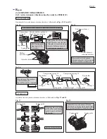
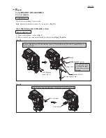
Connector
for connecting
to Controller
Lead wire holder
Lead wire holder
covered with Sponge
sheet
Fix Lead wires with
Sponge sheet and
Lead wire holder.
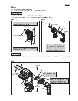
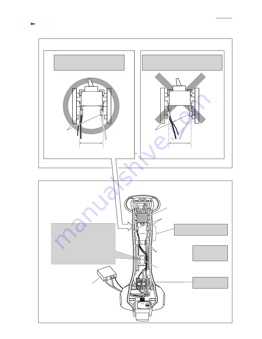
Wiring to Switch
Wiring in Handle
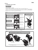
Connect Insulated connector to Switch
so that the clamped portions are in the
width of Switch.
If the clamped portions of insulated connectors
were out of width of Switch, they would inter-
fere in installing the switch as shown below.
Switch
Switch
Switch
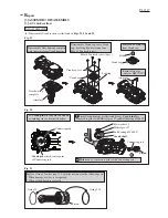
The following Lead wires have
to be put on the Lead wire (thin,
black) connecting Switch and
Controller, in this Lead wire holder.
* Lead wire (thick, black) connecting
Switch and Terminal block,
* Lead wire (thick, white) connecting
Switch and Controller
Insulated connector
Expand the Lead wires between
Switch and Lead wire holder.
Fix Lead wires with
Lead wire holder.
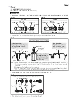
Fig. D-3
Fig. D-4
The clamped
portions
face inside.
The clamped
portions
face outside.
the width of
Switch
the width of
Switch

