16 ENGLISH
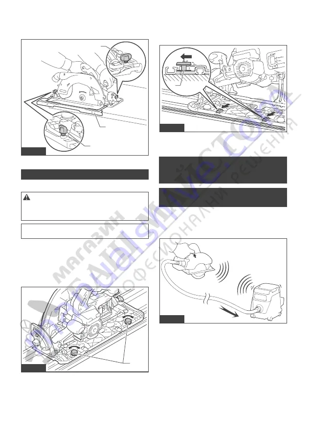
Simply slide the fence of the sub base snugly against
the side of the workpiece and secure it in position with
the clamping screws. It also makes repeated cuts of
uniform width possible.
1
2
1
Fig.31
►
1.
Clamping screw
2.
Sub base
Guide rail
Optional accessory
CAUTION:
Always be sure that the tool is
switched off and the battery cartridge is removed
before loosening the adjusting screws on the tool
base.
NOTICE:
Remove the sub base when using the
guide rail.
Place the tool on the rear end of guide rail. Turn two
adjusting screws on the tool base so that the tool slides
smoothly without a clatter. Hold both the front grip and
rear handle of the tool firmly. Install the battery car
-
tridge. Turn on the tool and cut the splinter-guard along
the full length with a stroke. Now the edge of the splin-
ter-guard corresponds to the cutting edge.
1
Fig.32
►
1.
Adjusting screws
When bevel cutting with the guide rail, use the slide
lever to prevent the tool from falling over.
Move the slide lever on the tool base in the direction
of arrow so that it engages the undercut groove in the
guide rail.
1
Fig.33
►
1.
Slide lever
WIRELESS ACTIVATION
FUNCTION
What you can do with the wireless
activation function
The wireless activation function enables clean and com-
fortable operation. By connecting a supported vacuum
cleaner to the tool, you can run the vacuum cleaner
automatically along with the switch operation of the tool.
Fig.34
To use the wireless activation function, prepare follow-
ing items:
•
A wireless unit (optional accessory)
•
A vacuum cleaner which supports the wireless
activation function
The overview of the wireless activation function
setting is as follows. Refer to each section for detail
procedures.
1.
Installing the wireless unit
2.
Tool registration for the vacuum cleaner
3.
Starting the wireless activation function


