

R
epair
P 2 / 8
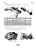
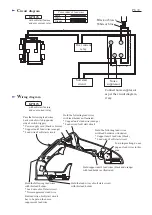
< 1 > Lubrication
Apply MAKITA grease N. No.1 to the following portions marked with black triangle to protect
parts and product from unusual abrasion.
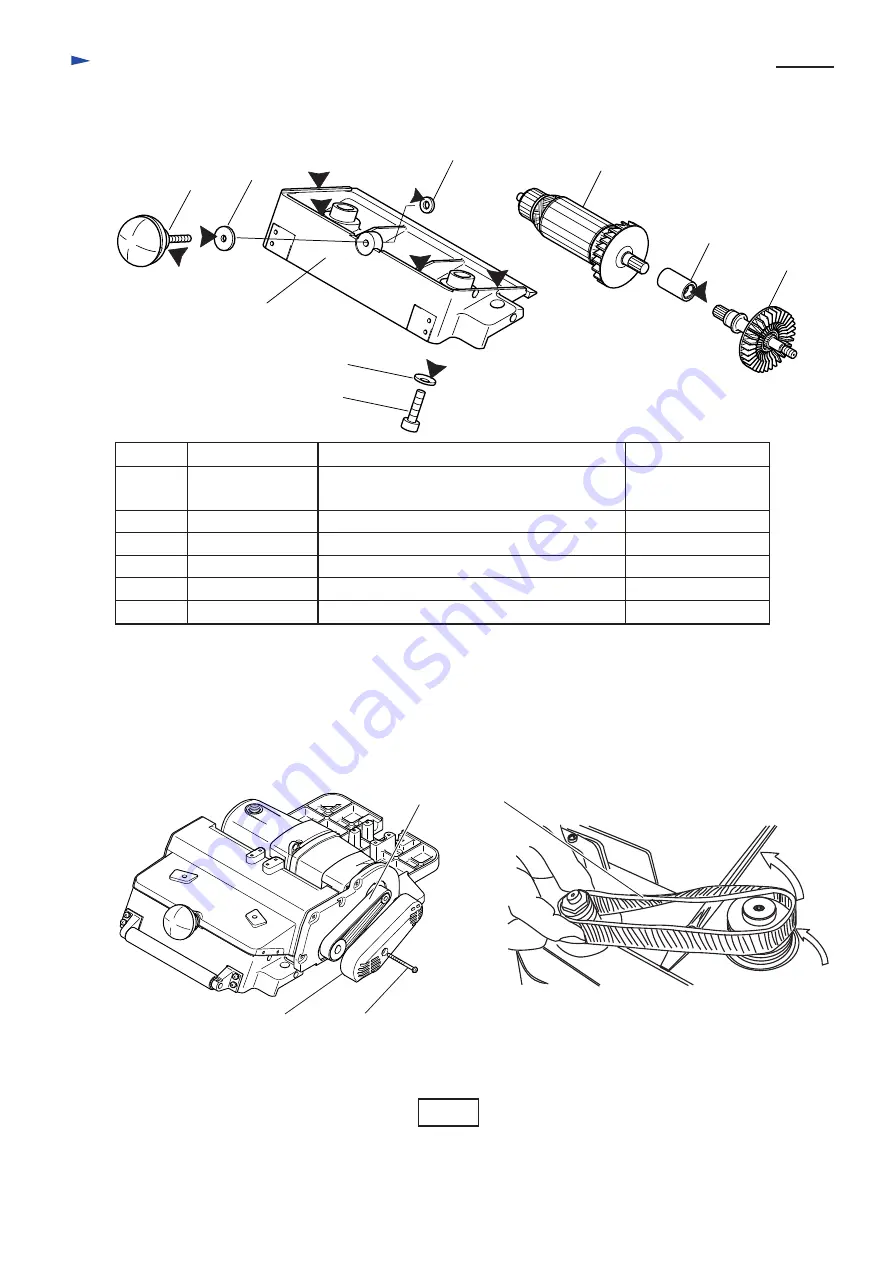
< 2 > Removing poly V belt
( 1 ) Remove belt cover by unscrewing one pc. of pan head screw M5x65.
( 2 ) Lifting up poly V belt with screwdriver, turn V pulley with your hand.
Then, V pulley can be removed as illustrated in Fig. 1.
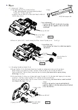
Fig. 1
hex socket head
bolt M10x40
(86)
(67)
(46)
(74)
(68)
(69)
Item No.
Descriptions
Portions to be lubricated
Amount to be applied
Approx. 4g (0.14 oz)
Approx. 1g (0.04 oz)
67
46
Flat washer 8
Coupling
Whole portion
Inner hole (spline portion) which accepts
armature shaft and spindle
68
Flat washer 8
The portion where knob (69) contacts.
69
Knob
74
Front base
The portion where flat washer 8 (68) contacts.
The portion where main base contacts.
86
Leaf spring
The portion where front base contacts.
Armature
Spindle
complete
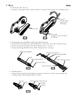
Pan head screw
M5x65
Belt cover
Poly V belt


