
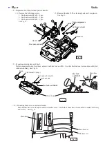

C
ircuit diagram
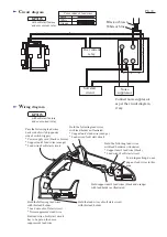
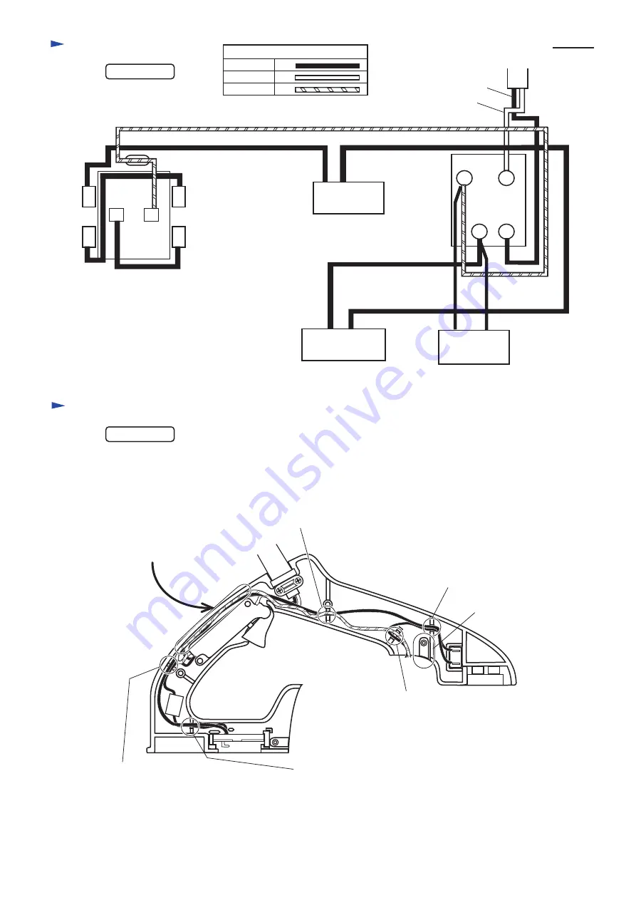
W
iring diagram
P 8 / 8
Color index of lead wires
Black
with soft start feature
and over current relay
White
Orange
2
4
5
3
Over current
relay
Noise
suppressor
Soft start
circuit
White or blue
Black or brown
KP312S
KP312S
Connect noise suppressor
as per the circuit diagram,
if any.
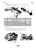
To avoid pinching, do not
pup any lead wires in this
area.
Hold the following lead wires
with lead holders as illustrated.
* Support unit's lead wire (black )
* Lead wire of soft start circuit
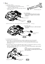
Hold the following lead wires
with lead holder as illustrated.
* Support unit's lead wire (orange )
* Lead wire of soft start circuit
Hold support unit's lead wires (black and orange)
with lead holder as illustrated.
Hold the following lead wires
with this lead holder.
* Lead wire of soft start circuit
* Noise suppressor's lead wire
But lead wire of soft start circuit
has to be put on the noise
suppressor's lead wire.
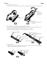
Hold the lead wires of soft start circuit
with this lead holder.
Pass the following lead wires
back side of switch (opposite
side of switch trigger.)
* Power supply cord (black or brown)
* Support unit's lead wires (orange)
* Lead wire of soft start circuit
with soft start feature
and over current relay


