


7 ENGLISH
Additional safety warnings
1.
Watch out for flying sparks when operating.
They can cause injury or ignite combustible
materials.
2.
Secure work. Use clamps or a vise to hold
work when practical.
It's safer than using your
hand and it frees both hands to operate tool.
3.
Secure the wheel carefully.
4.
Be careful not to damage the spindle, flanges
(especially the installing surface) or bolt, or
the wheel itself might break.
5.
Keep guards in place and in working order.
6.
Hold the handle firmly.
7.
Keep hands away from rotating parts.
8.
Make sure the wheel is not contacting the
work-piece before the switch is turned on.
9.
Before each use, watch for flutter or excessive
vibration that might be caused by poor instal-
lation or a poorly balanced wheel.
10.
Remove material or debris from the area
that might be ignited by sparks. Be sure that
others are not in the path of the sparks. Keep
a proper, charged fire extinguisher closely
available.
11.
If the wheel stops during the operation, makes
an odd noise or begins to vibrate, switch off
the tool immediately.
12.
Always switch off and wait for the wheel to
come to a complete stop before removing,
securing workpiece, working vise, changing
work position, angle or the wheel itself.
13.
Do not touch the workpiece immediately after
operation; it is extremely hot and could burn
your skin.
14.
Store wheels in a dry location only.
SAVE THESE INSTRUCTIONS.
INSTALLATION
WARNING:
This tool produces spark when
cutting a workpiece. Do not install this tool in
the place in which flammable and/or explosive
materials might be ignited by the spark from the
tool. Also make sure that there is no such material
near the tool before starting the operation.
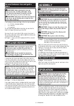
Securing the base
This tool should be bolted with two bolts to a level and
stable surface using the bolt holes provided in the tool's
base. This will help prevent tipping over and possible
personal injury.
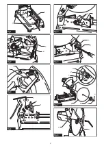
►
Fig.1:
1.
Bolt holes
2.
Base
FUNCTIONAL
DESCRIPTION
CAUTION:
Always be sure that the tool is
switched off and unplugged before adjusting or
checking function on the tool.
Unlocking/locking tool head
The tool head can be locked.
When using, unhook the lock chain from the hook.
When not in use or carrying, always hook the lock chain
to the hook.
►
Fig.2:
1.
Hook
2.
Lock chain
Switch action
WARNING:
Before plugging in the tool,
always check to see that the switch trigger actu-
ates properly and returns to the "OFF" position
when released.
►
Fig.3:
1.
Lock button / Lock-off button
2.
Switch
trigger
For tool with lock button
To start the tool, simply pull the switch trigger. Release
the switch trigger to stop. For continuous operation,
pull the switch trigger, push in the lock button and then
release the switch trigger. To stop the tool from the
locked position, pull the trigger fully, then release it.
CAUTION:
Switch can be locked in "ON" posi-
tion for ease of operator comfort during extended
use. Apply caution when locking tool in "ON"
position and maintain firm grasp on tool.
For tool with lock-off button
To prevent the switch trigger from being accidentally
pulled, a lock-off button is provided. To start the tool,
press the lock-off button and pull the switch trigger.
Release the switch trigger to stop.
WARNING:
NEVER defeat the lock-off button
by taping down or some other means.
A switch with
a negated lock-off button may result in unintentional
operation and serious personal injury.
WARNING:
NEVER use the tool if it runs when
you simply pull the switch trigger without press-
ing the lock-off button.
A switch in need of repair
may result in unintentional operation and serious
personal injury. Return tool to a Makita service center
for proper repairs BEFORE further usage.
NOTICE:
Do not pull the switch trigger hard
without pressing in the lock-off button.
This can
cause switch breakage.


