background image

6

FUNCTIONAL 
DESCRIPTION

CAUTION:

Always be sure that the tool is switched off and
unplugged before adjusting or checking function on the
tool.

Adjusting depth of cut

Depth of cut may be adjusted by simply turning the knob on
the front of the tool.

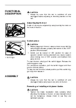
Switch action

CAUTION:

Before plugging in the tool, always check to see that the
switch trigger actuates properly and returns to the “OFF”
position when released.

Switch can be locked in “ON” position for ease of
operator comfort during extended use. Apply caution
when locking tool in “ON” position and maintain firm
grasp on tool.

To start the tool, simply pull the switch trigger. Release the
switch trigger to stop.
For continuous operation, pull the switch trigger and then
push in the lock button.
To stop the tool from the locked position, pull the switch trig-
ger fully, then release it.

ASSEMBLY

CAUTION:

Always be sure that the tool is switched off and
unplugged before carrying out any work on the tool.

Removing or installing mini planer blades

CAUTION:

Tighten the blade installation bolts carefully when
attaching the blades to the tool. A loose installation bolt
can be dangerous. Always check to see they are
tightened securely.

002549

1. Lock button

2. Switch trigger

1

2

002553

Summary of Contents for N1900B

Page 1: ...I O N M A N U A L WARNING For your personal safety READ and UNDERSTAND before using SAVE THESE INSTRUCTIONS FOR FUTURE REFERENCE w w w m a k i t a t o o l s c o m Power Planer 82 mm 3 1 4 MODEL N1900B DOUBLE INSULATION ...

Page 2: ... in the presence of flammable liquids gases or dust Power tools create sparks which may ignite the dust or fumes 3 Keep bystanders children and visitors away while operating a power tool Distrac tions can cause you to lose control Electrical Safety 4 Double insulated tools are equipped with a polarized plug one blade is wider than the other This plug will fit in a polarized outlet only one way If ...

Page 3: ...wrench or a key that is left attached to a rotating part of the tool may result in personal injury 13 Do not overreach Keep proper footing and balance at all times Proper footing and balance enables better control of the tool in unexpected situations 14 Use safety equipment Always wear eye protection Dust mask non skid safety shoes hard hat or hearing protection must be used for appropriate condit...

Page 4: ...ate ampere rating If in doubt use the next heavier gage The smaller the gage num ber the heavier the cord SPECIFIC SAFETY RULES USB042 2 DO NOT let comfort or familiarity with product gained from repeated use replace strict adherence to planer safety rules If you use this tool unsafely or incorrectly you can suffer serious personal injury 1 Rags cloth cord string and the like should never be left ...

Page 5: ...the tool only when hand held 14 When leaving the planer switch off and set it with the front base up on a wooden block so that the blades do not contact anything 15 Always change both blades or covers on the drum otherwise the resulting imbal ance will cause vibration and shorten tool life 16 Wait for complete run down before putting the tool aside 17 Use only Makita blades specified in this manua...

Page 6: ...n locking tool in ON position and maintain firm grasp on tool To start the tool simply pull the switch trigger Release the switch trigger to stop For continuous operation pull the switch trigger and then push in the lock button To stop the tool from the locked position pull the switch trig ger fully then release it ASSEMBLY CAUTION Always be sure that the tool is switched off and unplugged before ...

Page 7: ...ge base so that the cutting edge of the blade is perfectly flush with the inside flank of the gauge plate 3 Set the adjusting plate set plate on the gauge base so that the planer blade locating lugs on the set plate rest in the mini planer blade groove then press in the heel of the adjusting plate flush with the back side of the gauge base and tighten the pan head screws 4 It is important that the...

Page 8: ...e other 8 Tighten the three hex flange head bolts with the socket wrench provided and hand rotate the drum to check clearances between the blade ends and the tool body 9 Check the three hex flange head bolts for final tightness 10 Repeat procedures 1 9 for other blade Planer blade adjustment optional accessory To install the blades first clean out all chips or foreign matter adhering to the drum o...

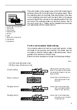
Page 9: ...ust be mounted so that the cutting edge is absolutely level that is parallel to the surface of the rear base Below are some examples of proper and improper settings 1 Inside edge of gauge plate 2 Blade edge 3 Planer blade 4 Adjusting plate 5 Screws 6 Heel 7 Back side of gauge base 8 Gauge plate 9 Gauge base 1 2 3 4 5 6 7 8 9 002556 A B B A B A A Front base Movable shoe B Rear base Stationary shoe ...

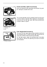
Page 10: ...le Use the chip cover screws to fasten it in place Dust bag optional accessory The use of the dust bag makes cutting operations clean and dust collection easy To attach the dust bag first remove the chip cover and then install the dust bag assembly For the best results empty the dust bag when it becomes about half full Remove the dust bag from the tool and pull out the fastener 1 Nozzle assembly 1...

Page 11: ...r rough cutting the depth of cut can be increased while for a good finish you should reduce the depth of cut and advance the tool more slowly Shiplapping Rabbeting To make a stepped cut as shown in the figure use the edge fence guide rule Draw a cutting line on the workpiece Insert the edge fence into the hole in the front of the tool Align the blade edge with the cutting line Adjust the edge fenc...

Page 12: ...gn the V groove in the front base with the edge of the workpiece and plane it MAINTENANCE CAUTION Always be sure that the tool is switched off and unplugged before attempting to perform inspection or maintenance Sharpening the planer blades optional accessory Always keep your blades sharp for the best performance possible Use the sharpening holder optional accessory to remove nicks and produce a f...

Page 13: ... simultaneous sharpening at the same angle Replacing carbon brushes Remove and check the carbon brushes regularly Replace when they wear down to the limit mark Keep the carbon brushes clean and free to slip in the holders Both carbon brushes should be replaced at the same time Use only iden tical carbon brushes Use a screwdriver to remove the chip cover 1 Wing nut 2 Blade A 3 Blade B 4 Side D 5 Si...

Page 14: ...r Makita tool specified in this manual The use of any other accessories or attachments might present a risk of injury to persons Only use accessory or attachment for its stated purpose If you need any assistance for more details regarding these accessories ask your local Makita service center High speed steel Planer blade Tungsten carbide Planer blade For longer blade life Mini planer blade Sharpe...

Page 15: ...Memo 15 ...

Page 16: ...Memo 16 ...

Page 17: ...17 First Class Postage Required Post Office will not deliver without proper postage Makita U S A Inc 14930 Northam Street La Mirada CA 90638 5753 Fold Cut ...

Page 18: ...ability Power Other Design Features Size Price Makita Brand 5 Any comments MAIL THIS PORTION Your answers to the following questions are appreciated BE SURE TO COMPLETE THE CUSTOMER S PORTION OF THIS FORM AND RETAIN FOR YOUR RECORDS DATE PURCHASED MODEL NO SERIAL NO INTL LAST NAME COMPANY NAME STREET ADRESS CITY STATE AGE ZIP CODE PHONE AREA CODE STATUS Married SEX M F Single MONTH DAY YEAR Under ...

Page 19: ... St Louis MO 63126 2221 314 909 9889 NEBRASKA 4129 S 84th St Omaha NE 68127 402 597 2925 NEVADA 3375 S Decatur Blvd Suites 22 24 Las Vegas NV 89102 702 368 4277 NEW JERSEY 251 Herrod Blvd Dayton NJ 08810 1539 609 655 1212 NEW YORK 4917 Genessee Street Cheektowaga NY 14225 716 685 9503 OREGON 828 19th Avenue N W Portland OR 97209 503 222 1823 PENNSYLVANIA 1704 Babcock Blvd Pittsburgh PA 15209 412 8...

Page 20: ...one of Makita s Factory or Authorized Service Centers If inspection shows the trouble is caused by defective workmanship or material Makita will repair or at our option replace without charge This Warranty does not apply where repairs have been made or attempted by others repairs are required because of normal wear and tear the tool has been abused misused or improperly maintained alterations have...

Reviews: