background image

Summary of Contents for PLANER 2040

Page 1: ...height No load speed 12 7mm 1 9 5 m m 6 500 In 1112 7 518 400 mm 15 3 4 MODEL 2040 2 9 m mm 129 5 ftimin 1 396 mm x 600 nim 115 5 8 x 23 5 8 1 Overall dimenslons W x L x HI 570 mm x 1 0251 1 1 1 1 1x 715 rnnl Net weight 115 k g 254Ibsl 122 112 x 40 318 x 28 1 1 8 l INSTRUCTION MANUAL SPECIFICATIONS 396 mm I1 5 518 ...

Page 2: ... 8 DON T FORCE TOOL It will do the job better and safer at the rate for which it was designed 9 USE RIGHT TOOL Don t force tool or attachment to do a job for which it was not designed 10 WEAR PROPER APPAREL Wear no loose clothing gloves neckties rings bracelets or other jewelry which may get caught in moving parts Nonslip footwear is recommended Wear protective hair covering to contain long hair 1...

Page 3: ...MAGED PARTS Before further use of the tool a guard or otht part that is damaged should be carefully checked to determine that it wi operate properly and perform its intended function check for alignmer of moving parts binding of moving parts breakage of parts mounting an any other conditions that may affect its operation A guard or other part thc is damaged should be properly repaired or replaced ...

Page 4: ...quipment grounding conductor can result in a risk of electric shock The conductor with insulation having an outer surface that is green with or without yellow stripes is the equipment grounding conductor If repair or replacement of the electric cord or plug is necessary do not connect the equipment grounding conductor to a live terminal Check with a qualified electrician or serviceman if the groun...

Page 5: ...utting 12 Keep hands away from rotating parts 13 Don t back the workpiece toward the infeed table 14 Two or more pieces of narrow but similar thickness stock can be passed through the auto planer side by side However allow some spacing between the stock to permit the feed rollers to grip the thinnest piece Otherwise a slightly thinner piece could be kicked back by the cutterhead 15 Stop operation ...

Page 6: ...he specified amount in one pass Make two passes rather than put an over loadon the planer that might cause trouble Gauge height shows the amount of cut Fig 1 OEP 118 I3 mml 3m4 11 mml c 1I 16 314 1150mml 1300mml 1400mml WIDTH Stock feed Align the stock to be cut with the top of the table If the stock is too thick to be cut immediately lower the table by means of the crank handleso as to reduce the...

Page 7: ...ery simply just by setting the stopper ring to the desired dimension Do not crank the handle so hard that you force the stopper ring to move Fig 4 Key safety switch This machine can only be switchedon after the key is inserted in the switch The key can be removed with the switch in the ON condition and the tool may be switched off without the key When unattended the machine should be both OFF and ...

Page 8: ...he cutter drum as shown in Fig 6 Next release the lever to make the drum stationary Fig b Remove the 8 hex bolts with the socket wrench provided then take off the drum cover cutter retaining plate Use the end of the socket wrench handle to push the cutter out slightly Raise the lever once more makingthe drum stationary at the posi tion seen in Fig 7 then remove the cutter knife Cutter knife Drum c...

Page 9: ...ts fully in order may cause the knife to move At first tighten bolts gradually and evenly be fore applying the final tightening torque c Secure the lever at the position you found it a t when the chip guard was raised then set the lever on top see right pressing down very gently and turning the cutter drum in the arrow direction The leveller should move the same amount when placed over either end ...

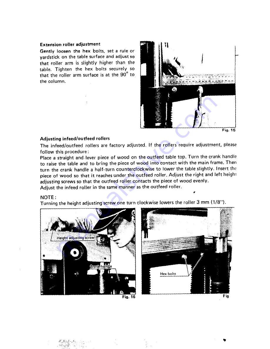
Page 10: ...wn causes the bed roller to lower NOTE The above adjustment procedure shouldbe Range of groove rotation on roller adjuster to adjust height of bed roller left Range of groove roation on roller adjuster to adjust of bed roller right Fig 1 1 Caution Unless the twogroove positions on the one roller face the same direction the stock may be twistedto the left or right I f the rollers protrude too much ...

Page 11: ... to raise the table and to bring the piece of wood into contact with the main frame Then turn the crank handle a half turncounterclockwiseto lower the table slightly Insert the piece of wood so that it reachesunder the outfeed roller Adjust the right and left heighi adjustingscrews so that the outfeed roller contacts the pieceof wood evenly Adjust the infeed roller in the same manner as the outfee...

Page 12: ...arbon brushes should be replaced a t the ame time Use only identical carbon rushes 5 Limit mark Fig II nsert a minus screwdriver into the holes for carbon brush changeover on the base of the daner Remove the brush holder cap and take out the worn carbon brush Replace with new carbon brushes then reinstall the brush holder caps and both holders eaning iways brush off dirt chips and foreign atter ad...

Page 13: ...machine oil Oiling should be done with tool not operating To maintain product SAFETY and RELIABILITY repairs any other maintenance or adjustment should be performed by Makita Authorized or Factory Service Centers always using Makita replacementparts 13 ...

Page 14: ...l The use of any other accessories or attachments might present a risk of injury to persons The accessories or attachments hsould be used only in the proper and intended manner 0 Replacement blades 400 mm 15 3 4 1 Part No 731024 2 Sprocket set For Low Speed Feed Part No 191440 4 f i t A 0 Planer stand Part No 122192 3A c 14 ...

Page 15: ...15 ...

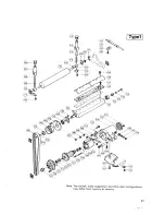
Page 16: ...MODEL 2040 c Jan 08 96 Us c 16 ...

Page 17: ...17 ...

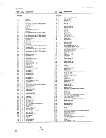
Page 18: ...ng Washer 6 Hex Nut M 6 Pan Head Screw M6r50 Hex Not M I 2 Spring Wayher I 2 Flat Waihrr I 2 Rmq 46 Handle Supgorlrr Woodrull Key 4 Handle Shalt 1 14 79 80 61 82 83 84 85 86 87 88 89 90 91 92 93 94 95 96 97 98 99 00 01 02 03 04 05 06 07 08 09 IO 11 I 2 13 14 15 16 17 18 19 20 21 22 23 24 25 26 27 28 29 30 31 32 33 34 35 36 37 38 39 40 11 12 13 14 15 16 1 1 I I 1 1 1 1 4 4 2 4 4 1 4 1 1 5 1 1 4 8 4...

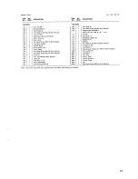
Page 19: ...hell Pan Head Screw M5x30 lWilh Warherl P DleC Dl Hex Bolt M8 30 With Washer1 Stop Ring E 15 FIELD ASSEMBLY Ball Bearing 6200LLB m y e PI 168 169 I 7 0 I 7 1 172 173 174 175 176 177 I 7 8 179 1BO 900 901 903 904 905 906 908 1 2 1 1 1 1 1 1 4 1 1 I I 1 2 1 I 1 1 2 Dust Seal 10 Pan Heed Screw M5195 IWilh Warherl ARMATUAE ASSEMBLY IWilh Iten 167 168 LL 170 1731 Fan 92 Dust Seal 12 BAII nearnng 6 2 0 ...

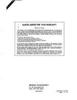
Page 20: ...improperly maintained alterations have been made to the 1001 IN NO EVFNT SHALL MAKITA BE LIABLE FOR ANY INDIRECT INCIDENTAL OR CON SEQUENTIAL DAMAGES FROM THE SALE OR USE O F THE P R O D k T THIS DISCLAIMER APPLIES BOTH DURING AND AFTER THE TERM O F THIS WARRANTY MAKITA DISCLAIMS LIABILITY FOR ANY IMPLIED WARRANTIES INCLUDING IMPLIED WARRANTIES O F MERCHANTABILITY AND FITNESS FOR A SPECIFIC PURPOS...

Reviews: