21 ENGLISH
Overdischarge protection
When the battery capacity is not enough, the machine
stops automatically and the main power lamp blinks in
red. In this case, remove the battery from the machine
and charge the battery or change the battery to fully
charged one.
Protections against other causes
Protection system is also designed for other causes that
could damage the machine and allows the machine to
stop automatically. Take all the following steps to clear
the causes, when the machine has been brought to a
temporary halt or stop in operation.
1. Turn the machine off, and then turn it on again to
restart.
2. Charge the battery(ies) or replace it/them with
recharged battery(ies).
3. Let the machine and battery(ies) cool down.
If no improvement can be found by restoring protection
system, then contact your local Makita Service Center.
NOTICE:
If the machine stops due to a cause
not described above, refer to the section for
troubleshooting.
Main power switch
WARNING:
Always turn off the main power
switch when not in use.
To turn on the machine, press the main power switch.
The lamps light up in green. To turn off, press and hold
the main power switch until the lamps go off.
►
Fig.19:
1.
Speed indicator
2.
Main power switch
The speed can be changed in three levels. To change
the speed mode, press the main power switch. When
you change the speed mode, the corresponding speed
indicators light up.
NOTE:
The machine employs the auto power-off
function. To avoid unintentional start up, the main
power switch will automatically shut down when the
machine is not operated for a certain period after the
main power switch is turned on.
NOTE:
If the main power lamp lights up in red or
blinks in red or green, refer to the instructions for
machine/battery protection system.
Switch action
WARNING:
Before installing the battery car-
tridge into the machine, always check to see that
the switch trigger actuates properly and returns
to the “OFF” position when released.
To start the machine, pull the switch trigger. The speed
increases by increasing pressure on the switch trigger.
Release the switch trigger to stop.
►
Fig.20:
1.
Switch trigger
Cruise control function
The cruise control function allows the operator to main-
tain a constant speed without pulling the trigger. To
increase the speed, turn the control lever forward. To
decrease the speed, turn the control lever backward.
►
Fig.21:
1.
Control lever
Opening and closing the levers
The machine is equipped with three levers.
Nozzle lever
The nozzle lever is used for blowing mist. Normally,
close the nozzle lever, and open the nozzle lever only
when blowing mist.
►
Fig.22:
1.
Closed
2.
Open
Draining lever
The draining lever is used for draining the liquid in the
tank. When operating the machine, always close the
lever.
►
Fig.23:
1.
Closed
2.
Open
Tank lever
The tank lever is used when replacing the filter. When
operating the machine, always open the lever.
►
Fig.24:
1.
Closed
2.
Open
Feed amount adjustment knob
You can adjust the amount of liquid fed to the end
nozzle. To feed the maximum amount of liquid, turn the
knob so that “4” is aligned with the triangular mark. To
feed the minimum amount of liquid, turn the knob so
that “1” is aligned with the triangular mark.
►
Fig.25:
1.
Feed amount adjustment knob
2.
Triangular mark
Electronic function
The machine is equipped with the electronic function for
easy operation.
•
Constant speed control
The speed control function provides the constant
rotation speed regardless of load conditions.
•
Feed valve function
The machine is equipped with the feed valve. The
feed valve automatically opens to feed the liquid
in the tank when the switch trigger is pulled, and
it automatically closes when the switch trigger is
released.
Accidental re-start preventive
function
When you turn on the machine while pulling the switch
trigger, the machine does not start and the main power
lamp blinks in green. To start the machine, first release
the switch trigger and return the control lever fully, and
then turn on the machine.
Summary of Contents for PM001G
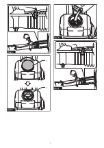
Page 2: ...2 0 30 30 Fig 1 1 Fig 2 1 2 3 Fig 3 6 1 2 3 4 5 Fig 4 2 1 4 3 5 Fig 5 ...
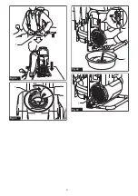
Page 3: ...3 3 2 1 Fig 6 1 Fig 7 1 2 Fig 8 1 Fig 9 1 Fig 10 ...
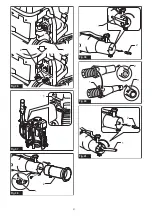
Page 4: ...4 1 2 3 Fig 11 1 Fig 12 1 Fig 13 1 2 Fig 14 1 Fig 15 1 Fig 16 ...
Page 5: ...5 1 2 Fig 17 1 2 Fig 18 1 2 Fig 19 1 Fig 20 1 Fig 21 1 2 Fig 22 ...
Page 6: ...6 1 2 Fig 23 1 2 Fig 24 2 1 Fig 25 1 Fig 26 1 Fig 27 ...
Page 7: ...7 1 Fig 28 1 2 Fig 29 Fig 30 1 Fig 31 ...
Page 8: ...8 1 Fig 32 1 Fig 33 1 2 Fig 34 1 Fig 35 ...
Page 9: ...9 2 1 Fig 36 1 Fig 37 1 2 Fig 38 1 2 Fig 39 1 2 3 Fig 40 1 2 Fig 41 ...
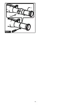
Page 10: ...10 1 2 Fig 42 ...
Page 99: ...99 ...

