background image

10

Safety instructions

Makita SK104

en

GB

F

I

E
P

NL

DK

S
N

FIN

J

CN

ROK

PL

HR

H

RUS

CZ

GR

LT
LV

EST
SLO

SK

M

TR

Safety instructions

The person responsible for the instrument must ensure 
that all users understand these directions and adhere to 
them.

Symbols used

The symbols used have the following meanings

WARNING:

Indicates a potentially hazardous situation or an 

unintended use which, if not avoided, will result in death 
or serious injury.

CAUTION:

Indicates a potentially hazardous situation or an 

unintended use which,if not avoided, may result in minor 
injury and/or appreciable material, financial and environ-
mental damage.

Important paragraphs which must be adhered

to in practice as they enable the product to be used
in a technically correct and efficient manner.

Permitted use

Projection of horizontal and vertical laser lines and 
laser dots

Prohibited use

Using the product without instruction

Using outside the stated limits

Deactivation of safety systems and removal of 
explanatory and hazard labels

Opening of the equipment by using tools (screw-
drivers, etc.), as far as not specifically permitted for 
certain cases

Carrying out modification or conversion of the 
product

Deliberate dazzling of third parties; also in the dark

Inadequate safeguards at the surveying site.

Limits of use

Refer to section "Technical data".

The SK104 is designed for use in areas permanently 
habitable by humans. Do not use the product in explo-
sion hazardous areas or in aggressive environments.

Areas of responsibility

Responsibilities of the manufacturer of the original 
equipment:

Makita Corporation Anjo, 3-11-8, Sumiyoshi-cho, Aichi 
446-8502, Japan /
Makita, Jan-Baptist Vinkstraat 2, 3070, Belgium
Internet: www.makita.com (for short Makita):

Makita is responsible for supplying the device, including 
the User Manual, in a completely safe condition.

Makita is not responsible for third party accessories.

Summary of Contents for SK104Z

Page 1: ... Operation 2 Care and advice on operation 8 Transport 8 Technical data SK104 9 Safety instructions 10 Start up Inserting replacing batteries Pull the battery cover outwards to unlock the battery compartment Open the battery compartment cover and insert the batteries observing the correct polarity Then press the battery compartment cover back down until it engages Insert the batteries observing the...

Page 2: ... Laser active 6 Pulse Power save mode ON Switching on off ON Briefly press the On Set key 1 OFF Press and hold down the On Set key 1 Laser functions Pressing the On Set key 1 activates the following laser functions 3 Action SK104 not in Lock mode in Lock mode 1x only horizontal line only horizontal line 2x only vertical line only vertical line 3x horizontal and vertical line again as 1x 1 5 4 6 2 ...

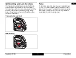
Page 3: ...h 3 in order to transport or tilt the instrument beyond the self levelling range When locked the pendulum is fixed and the self levelling function is deactivated Transportation and lock Self levelling Pulse To be able to detect the laser lines over long distances 15 m or in unfavourable lighting conditions a laser detector can be used The detector is able to locate the laser beam in Pulse mode eve...

Page 4: ...4 Operation Makita SK104 en GB F I E P NL DK S N FIN J CN ROK PL HR H RUS CZ GR LT LV EST SLO SK M TR Applications SK104 Receiver available as accessory ...

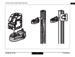
Page 5: ...5 Operation Makita SK104 en GB F I E P NL DK S N FIN J CN ROK PL HR H RUS CZ GR LT LV EST SLO SK M TR How to use the wall mount bracket ...

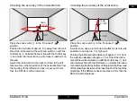
Page 6: ... the horizontal laser line or laser dot and mark the position of the line or the dot on wall A A1 Rotate the instrument by 180 and mark the horizontal laser line or the laser dot in exactly the same way on wall B B1 Then place the instrument at the same elevation as close as possible to wall A and again mark the horizontal laser line or the laser dot on wall A A2 Rotate the instrument by 180 again...

Page 7: ...m the marking If the difference does not exceed 3 mm then the SK104 is within tolerance Checking the accuracy of the vertical line Place the Lock switch 3 in the Unlocked position As reference use a plumb bob and attach it as close as possible to an approx 3 m high wall Position the instrument at a distance of approx 1 5 m from the wall at an elevation of approx 1 5 m Direct the instru ment at the...

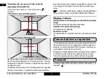
Page 8: ...ithin toler ance Should your SK104 be outside of the specified toler ance please contact an authorised dealership of Makita Display notices Falling below or exceeding the permissible temperature range The laser switches off and all symbols flash Outside of the self levelling range The laser beam is flashing Pendulum locked The laser beam is not levelled and the Lock symbol 4 lights up Care and adv...

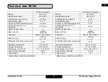
Page 9: ... Protection class spray water dust IP 54 Operating temperature 10 C to 40 C Storage temperature 25 C to 70 C Dimensions H x D x W 111 x 117 x 72 mm Weight without batteries 470 g Tripod thread 1 4 Non metric unit system Range up to 50 ft Range with detector up to 197 ft Levelling accuracy 32 ft 1 8 Self levelling range 4 1 Accuracy of horizontal line 32 ft 1 8 Vertical accuracy 10 ft line length 0...

Page 10: ... laser dots Prohibited use Using the product without instruction Using outside the stated limits Deactivation of safety systems and removal of explanatory and hazard labels Opening of the equipment by using tools screw drivers etc as far as not specifically permitted for certain cases Carrying out modification or conversion of the product Deliberate dazzling of third parties also in the dark Inade...

Page 11: ... in accordance with national or local regulations The product must not be disposed of with the household waste Dispose of the product appropriately in accordance with the national regulations in force in your country Always prevent access to the product by unau thorised personnel WARNING Using a battery charger not recommended by Makita can destroy the batteries This can cause fire or explosions P...

Page 12: ... which can be determined by turning the equipment off and on the user is encour aged to try to correct the interference by one or more of the following measures Reorient or relocate the receiving antenna Increase the separation between the equipment and receiver Connect the equipment into an outlet on a circuit different from that to which the receiver is connected Consult the dealer or an experie...

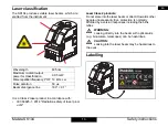
Page 13: ...lass 2 products Do not stare into the laser beam or direct it towards other people unnecessarily Eye protection is normally afforded by aversion responses including the blink reflex WARNING Looking directly into the beam with optical aids e g binoculars telescopes can be hazardous CAUTION Looking into the laser beam may be hazardous to the eyes Labelling Wavelength 635 nm Maximum radiant output po...

Reviews: