background image

R

epair

P 5 / 8 

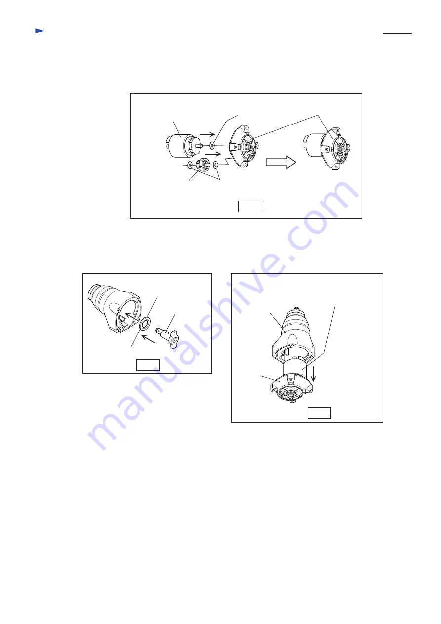
Fig.11

Fig.12

Fig.13

The hammer unit
(hammer, spindle, 
  compression spring 28, etc.)

Spur gear 19-41

Flat washer 8

Flat washer 8

( 4 ) Mount the hammer unit and spur gear 19-41 to the hammer case cover.   See Fig. 11.

( 5 ) Mount flat washer 19 and anvil to the hammer case.  See Fig. 12.

( 6 ) Mount hammer case cover as illustrated in Fig. 13.   The assembling of mechanical section has been finished
        at this step.

< Note >
   Do not forget to mount flat washers 8 to the following portion.
     * Spindle of hammer unit
     * Shaft of hammer case cover for spur gear 19-41  (both side of spur gear 19-41)    

This part can remain
in the hammer case.

Anvil

Flat washer 19

Hammer case

Hammer case
 cover

Hammer unit
(hammer, spindle, 
  compression spring 28, etc.)

Hammer 
case cover

Summary of Contents for TW0350

Page 1: ...9 1 8 87 3 7 16 Socket 24 45 1 pc Plastic carrying case 1 pc Socket 19 38 Socket 19 52 Socket 19 78 Socket 21 38 Socket 21 52 Socket 21 78 Socket 21 150 Socket 22 38 Socket 22 52 Socket 23 38 Socket...

Page 2: ...washer 8 contacts The joining hole in which 13 Spindle is inserted 19 cps of steel ball 4 Steel ball 6 4 Compression spring 28 Position No Parts item Portion to be lubricated Amount g oz 7 Flat washer...

Page 3: ...vil and flat washer 19 from hammer case See Fig 4 3 Remove the hammer unit and spur gear 19 41 and 3 pcs of flat washer 8 from hammer case cover See Fig 5 The parts can fall off the hammer case cover...

Page 4: ...been finished at this step 3 Putting the hammer unit as illustrated in Fig 7R remove the following parts Hammer Compression spring 28 Spring holder 19 pcs of steel ball 4 Spindle Hammer Compression sp...

Page 5: ...ase See Fig 12 6 Mount hammer case cover as illustrated in Fig 13 The assembling of mechanical section has been finished at this step Note Do not forget to mount flat washers 8 to the following portio...

Page 6: ...the sponge into the position as illustrated in Fig 15 3 Inflect the insulated terminals as illustrated in Fig 16 when connecting with switch terminals 37 34 38 40 42 39 49 48 Tapping screw 4x18 Tappin...

Page 7: ...ight Brush holder Left Brush holder Right Brush holder Left Brush holder Right Noise suppressor Terminal block Terminal block Power supply cord Power supply cord Resister Field Clear Purple Blue Brown...

Page 8: ...s lead holder Lead wire see through of noise suppressor Field lead wire purple to be connected to switch Field lead wire white to be connected to switch Field lead wire black to be connected to insula...

Reviews: