13 ENGLISH
Tips for maintaining maximum
battery life
1.
Charge the battery cartridge before completely
discharged. Always stop tool operation and
charge the battery cartridge when you notice
less tool power.
2.
Never recharge a fully charged battery car
-
tridge. Overcharging shortens the battery
service life.
3.
Charge the battery cartridge with room tem
-
perature at 10 °C - 40 °C (50 °F - 104 °F). Let
a hot battery cartridge cool down before
charging it.
4.
When not using the battery cartridge, remove
it from the tool or the charger.
5.
Charge the battery cartridge if you do not use
it for a long period (more than six months).
ASSEMBLY
CAUTION:
Always be sure that the machine is
switched off and the portable power pack is dis
-
connected from the machine before carrying out
any work on the machine.
Installing the end nozzle
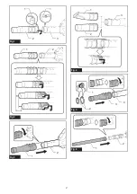
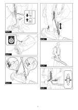
Align the triangle mark on the end nozzle with the trian-
gle mark on the front pipe, then attach the end nozzle
to the front pipe, and then turn the end nozzle to lock it
into place.
Install the end nozzle so that the tip of the nozzle faces
downward. Depending on the working environment, you
can install the end nozzle so that the tip of the nozzle is
facing up.
►
Fig.1:
1.
Triangle mark
2.
End nozzle
3.
Front pipe
To remove the end nozzle, perform the installation
procedure in reverse.
NOTE:
The length of the nozzle can be changed by
moving the nozzle as shown in the figure.
►
Fig.2:
1.
End nozzle
2.
Front pipe
Installing the flat nozzle or
extension nozzle
Optional accessory
1.
Align the groove on the adapter pipe with the pro-
trusion on the front pipe, then attach the adapter pipe to
the front pipe, and then turn it to lock it into place.
►
Fig.3:
1.
Adapter pipe
2.
Front pipe
2.
Align the groove on the flat nozzle or extension
nozzle with the protrusion on the adapter pipe, then
attach the flat nozzle or extension nozzle to the adapter
pipe, and then turn it to lock it into place.
►
Fig.4:
1.
Flat nozzle
2.
Extension nozzle
3.
Adapter
pipe
Installing the gutter nozzle set
Optional accessory
1.
Align the groove on the adapter pipe with the pro-
trusion on the front pipe, then attach the adapter pipe to
the front pipe, and then turn it to lock it into place.
Insert the adapter pipe as far as it will go so that the
protrusion fits into the deepest groove on the adapter
pipe.
►
Fig.5:
1.
Screw
2.
Hose clamp
3.
Adapter pipe
4.
Front pipe
2.
Loosen the screws on the hose clamps, and pass
the large hose clamp through the adapter pipe, and
then pass the small hose clamp.
3.
Connect the extension pipe to the adapter pipe.
Align the groove on the extension pipe with the protru-
sion on the adapter pipe, and then slide the extension
pipe along its groove so that the triangle markings face
each other.
►
Fig.6:
1.
Extension pipe
2.
Adapter pipe
4.
Place the hose clamps onto the grooves as illus-
trated and tighten the screws.
►
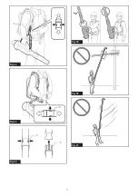
Fig.7:
1.
Screw
2.
Hose clamp
5.
According to the working height, connect the rest
of extension pipes to the extension pipe which has
already been attached.
CAUTION:
Do not attach the extension pipe
if the total length including the blower body
exceeds 4 m (14 ft).
6.
Turn the outlet of the end nozzle as shown in the
figure.
►
Fig.8
7.
Connect the end nozzle to the extension pipe.
When connecting, align the triangle marking on the end
nozzle and the extension pipe, and then push the end
nozzle until it clicks. After that, rotate the end nozzle to
a suitable position for your work.
►
Fig.9:
1.
End nozzle
2.
Extension pipe
3.
Triangle
marking
When removing the end nozzle, align the triangle mark-
ings on the end nozzle and extension pipe, and then
pull out the end nozzle from the extension pipe.
►
Fig.10:
1.
End nozzle
2.
Extension pipe
3.
Triangle
marking
Summary of Contents for UB001CZ
Page 2: ...2 3 1 1 Fig 1 1 2 Fig 2 2 1 Fig 3 1 3 2 Fig 4 2 3 1 4 Fig 5 2 1 Fig 6 2 ...
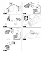
Page 3: ...1 2 2 Fig 7 Fig 8 1 2 3 Fig 9 1 2 3 Fig 10 1 2 Fig 11 1 Fig 12 3 ...
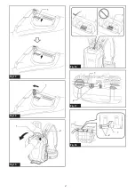
Page 4: ...1 Fig 13 1 Fig 14 2 1 Fig 15 1 Fig 16 1 2 Fig 17 2 1 Fig 18 4 ...
Page 5: ...1 Fig 19 1 2 Fig 20 1 2 Fig 21 2 1 Fig 22 Fig 23 1 2 Fig 24 Fig 25 5 ...
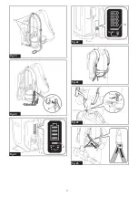
Page 6: ...1 2 3 Fig 26 1 Fig 27 Fig 28 Fig 29 Fig 30 1 Fig 31 6 ...
Page 7: ...1 Fig 32 1 Fig 33 1 1 Fig 34 Fig 35 Fig 36 Fig 37 7 ...
Page 8: ...15m 50ft Fig 38 Fig 39 Fig 40 1 Fig 41 1 Fig 42 8 ...
Page 110: ...10 ...
Page 111: ...11 ...
Page 112: ...IDE 885801 500 5 8 2020 Makita Europe N V Jan Baptist Vinkstraat 2 3070 Kortenberg Belgium ...


