12 ENGLISH
4.
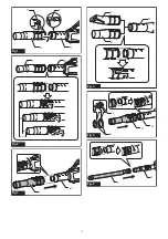
Place the hose clamps onto the grooves as illus-
trated and tighten the screws.
►
Fig.7:
1.
Screw
2.
Hose clamp
5.
According to the working height, connect the rest
of extension pipes to the extension pipe which has
already been attached.
CAUTION:
Do not attach the extension pipe
if the total length including the blower body
exceeds 4 m.
6.
Turn the outlet of the end nozzle as shown in the
figure.
►
Fig.8
7.
Connect the end nozzle to the extension pipe.
When connecting, align the triangle marking on the end
nozzle and the extension pipe, and then push the end
nozzle until it clicks. After that, rotate the end nozzle to
a suitable position for your work.
►
Fig.9:
1.
End nozzle
2.
Extension pipe
3.
Triangle
marking
When removing the end nozzle, align the triangle mark-
ings on the end nozzle and extension pipe, and then
pull out the end nozzle from the extension pipe.
►
Fig.10:
1.
End nozzle
2.
Extension pipe
3.
Triangle
marking
Attaching the shoulder strap
CAUTION:
When you use the machine in com
-
bination of the backpack-type power supply such
as portable power pack, do not use the shoulder
harness included in the machine package, but use
the hanging band recommended by Makita.
If you put on the shoulder harness included in the
machine package and the shoulder harness of the
backpack-type power supply at the same time,
removing the machine or backpack-type power supply
is difficult in case of an emergency, and it may cause
an accident or injury. For the recommended hanging
band, ask Makita Authorized Service Centers.
CAUTION:
Be sure to attach the hooks of
the shoulder strap to the machine securely.
If the
hooks are attached incompletely, they may come off
and cause an injury.
CAUTION:
Be sure to use the shoulder strap
dedicated to this machine.
Using other shoulder
strap may cause an injury.
Attach the hooks of the shoulder strap to the machine
as shown in the figure.
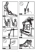
►
Fig.11:
1.
Hook
You can also attach the shoulder strap to the machine
as shown in the figure by attaching one end of the
shoulder strap to the buckle of the shoulder strap.
►
Fig.12:
1.
Buckle
FUNCTIONAL DESCRIPTION
CAUTION:
Always be sure that the machine is
switched off and the battery cartridge is removed
before adjusting or checking function on the
machine.
Installing or removing battery cartridge
CAUTION:
Always switch off the machine
before installing or removing of the battery
cartridge.
CAUTION:
Hold the machine and the battery
cartridge firmly when installing or removing bat
-
tery cartridge.
Failure to hold the machine and the
battery cartridge firmly may cause them to slip off
your hands and result in damage to the machine and
battery cartridge and a personal injury.
CAUTION:
Always install the battery cartridge
fully until the red indicator cannot be seen.
If not,
it may accidentally fall out of the machine, causing
injury to you or someone around you.
CAUTION:
Do not install the battery cartridge
forcibly.
If the cartridge does not slide in easily, it is
not being inserted correctly.
►
Fig.13:
1.
Red indicator
2.
Button
3.
Battery cartridge
To remove the battery cartridge, slide it from the machine
while sliding the button on the front of the cartridge.
To install the battery cartridge, align the tongue on the
battery cartridge with the groove in the housing and slip
it into place. Insert it all the way until it locks in place
with a little click. If you can see the red indicator as
shown in the figure, it is not locked completely.
Indicating the remaining battery capacity
Press the check button on the battery cartridge to indi
-
cate the remaining battery capacity. The indicator lamps
light up for a few seconds.
►
Fig.14:
1.
Indicator lamps
2.
Check button
Indicator lamps
Remaining
capacity
Lighted
Off
Blinking
75% to 100%
50% to 75%
25% to 50%
0% to 25%
Charge the
battery.
The battery
may have
malfunctioned.
Summary of Contents for UB001G
Page 2: ...2 3 1 1 Fig 1 1 2 Fig 2 2 1 Fig 3 1 3 2 Fig 4 2 3 1 4 Fig 5 2 1 Fig 6 2 ...
Page 3: ...1 2 2 Fig 7 Fig 8 1 2 3 Fig 9 1 2 3 Fig 10 1 1 Fig 11 1 Fig 12 3 ...
Page 4: ...2 3 1 1 Fig 13 1 2 Fig 14 1 2 Fig 15 1 Fig 16 1 Fig 17 1 Fig 18 4 ...
Page 5: ...Fig 19 Fig 20 Fig 21 Fig 22 15m Fig 23 Fig 24 Fig 25 5 ...
Page 6: ...1 Fig 26 1 Fig 27 6 ...
Page 101: ...101 ...
Page 102: ...102 ...
Page 103: ...103 ...

