background image


P  

3

8

R

epair

[3] DISASSEMBLY/ASSEMBLY

[3] -2. Fan Section

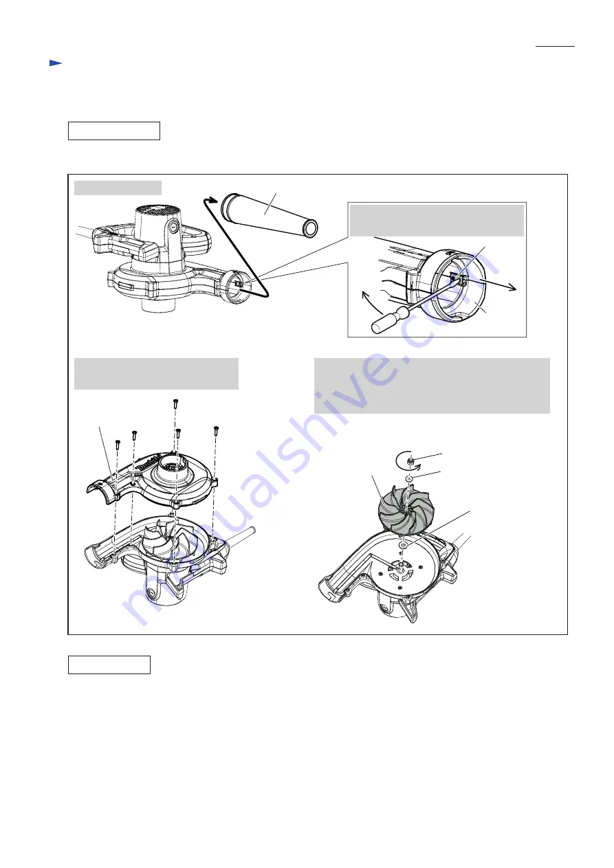
DISASSEMBLING

Disassemble Fan 110 as drawn in 

Fig. 2

.

Assemble Fan Section by reversing the disassembly procedure. Refer to 

Fig. 2

.

Note: 

Align the hole on Set plate with the protrusion on Fan cover, and insert Set plate by hand, then push it


with a small screwdriver until it stops. 


Refer to the drawing on


the

 top right

 in 

Fig. 2.

Fig. 2

ASSEMBLING

Fan cover

Fan 110

M5-8 Hex nut

Flat washer 5

Flat washer 8

1. Remove Nozzle.

Nozzle

3. Unscrew five 4x18 Tapping screws

  and remove Fan cover.

4. Remove M5-8 Hex nut by turning it

 counterclockwise 

with an impact driver while

  holding Fan 110 firmly with 

a gloved hand

.

5. Remove Flat washer 5, Fan 110 and Flat washer 8.

Set plate

Fan cover

2. Remove Set plate by prying it off with

  a small slotted screwdriver.

Summary of Contents for UB1102

Page 1: ...lower Weight according to EPTA Procedure 01 2003 2 kg lbs Dust bag assembly Nozzle assembly Long nozzle assembly Flexible hose set Anchor nozzle set for vacuum function only Bending long nozzle set PR...

Page 2: ...ng Field Assemble Switch by reversing the disassembly procedure Refer to Fig 1 Note When mounting Handle cover be careful of the following Switch and Lead wire are not pinched with Handle cover Refer...

Page 3: ...mall screwdriver until it stops Refer to the drawing on the top right in Fig 2 Fig 2 ASSEMBLING Fan cover Fan 110 M5 8 Hex nut Flat washer 5 Flat washer 8 1 Remove Nozzle Nozzle 3 Unscrew five 4x18 Ta...

Page 4: ...2 Disassemble Fan section as drawn in Fig 2 3 Disassemble Armature as drawn in Fig 4 Fig 3 Fig 4 Flat washer 8 Armature Fan housing complete 1 Unscrew four 4x35 Tapping screws and disassemble Fan hou...

Page 5: ...rminal Field Field 1 Unscrew four 4x18 Tapping screws and remove Handle cover 3 Disconnect Ring terminals from Brush holders with a Slotted screwdriver Note Tapping the edge of Motor housing with a pl...

Page 6: ...l 1R370 Fig 7 1R063 Field 3 Connect field lead wires to Switch and mount Handle cover to Motor housing with four 4x18 Tapping screws Refer to the drawings on the top left and right in Fig 5 4 Insert A...

Page 7: ...Motor housing complete Wiring of Field lead wires connected to Switch Slit Field lead wires Lead wire holder 1 Mount Filed to Motor housing complete as shown below Lead wire white or blue of Power sup...

Page 8: ...Line filter if used Set Line filter with Field lead wires between Lead wire holders 1 Pass Field lead wires through Line filter and wind them one turn and pass them again as shown below 2 Winded Filed...

Reviews: