P 3/ 13
R
epair
DISASSEMBLING
Note: Unplug the machine from the power source. Remove Saw chain and Guide bar from the machine for safety
before repair/ maintenance.
Remove Chain oil from Oil tank in advance.
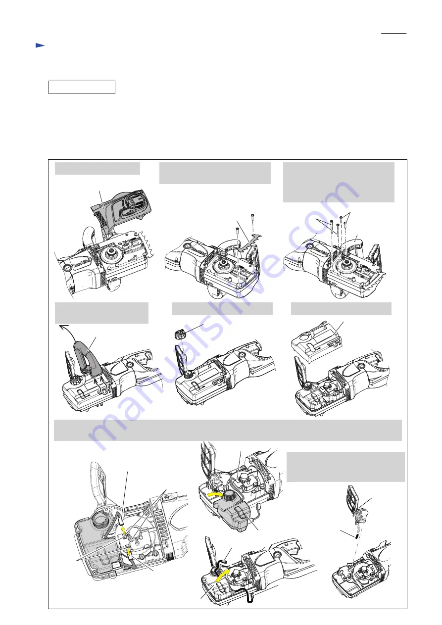
(1) Disassemble Gear housing cover side after removing Sprocket cover, Front handle and Spike bumper as drawn in
Fig. 2
.
1. Remove Sprocket cover.
3. Loosen two 5x25 Tapping screws
and two 5x60 Tapping screws
to remove Front handle from
the machine in the next step.
2. Loosen two 5x25 Tapping screws
to remove Spike bumper.
4. Turn over the machine and
remove Front handle.
6. Remove Gear housing cover.
7. Pull out Connector A straight from the nipple of Oil pump complete through Gear housing, then remove Oil tank
from Gear housing. When removing Oil pump complete, remove Connector B at this time.
8. Remove Front hand guard complete
Note
: Be careful not to pop out
Compression spring 6.
5. Remove Tank cap complete.
Fig. 2
[3] DISASSEMBLY/ASSEMBLY
[3]-1. Oil pump complete, Front hand guard complete
Front handle
5x25 Tapping
screw (2 pcs.)
5x60 Tapping
screw (2 pcs.)
Spike bumper
Front handle
Gear housing cover
Tank cap complete
Sprocket cover
Connector A
Connector A
Connector B
Nipples of Oil
pump complete
Cavities
of Gear
housing
Oil tank
Oil tank
Connector B
Connector B
Front hand
guard
complete
Compression
spring 6


