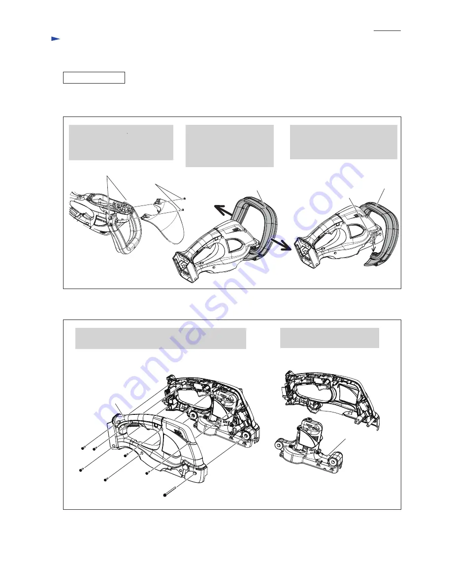
Fig. 4
Fig. 5
[3] DISASSEMBLY/ASSEMBLY
[3] -2. DC motor
DISASSEMBLING
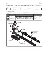
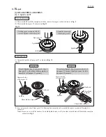
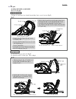
(1) Disassemble Shear blade complete and Spur gear 93 as drawn in
Fig. 2
.
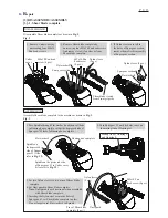
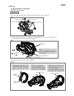
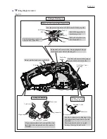
(2) Remove Protector and Front grip section as drawn in
Fig. 4
.
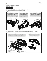
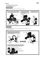
(3) Separate Housing R from Housing L. Then, remove Motor housing section from Housing L. See
Fig. 5
.
3x16 Tapping screw
(6 pcs.)
M4x65 Pan head screw
(1 pc.)
1. Remove Protector by unscrewing
two 4x18 Tapping screws.
And loosen two M5x25 Pan head
screws on the joints of Front grip.
1. Unscrewing six 3x16 Tapping screws and one M4x65
Pan head screw, separate Housing R from Housing L.
2.Separate Motor housing section
from Housing L.
2. Pulling Front grip toward
the direction designated
with arrow, remove it from
the holes on the both side
of Housing set.
3. Push Front grip along the grooves
on the both side of Housing set.
Front grip section is disassembled
from Housing set.
M5x25 Pan head
screw (2 pcs.)
Housing R
4x18 Tapping
screw (2 pcs.)
Motor housing section
groove
Front grip section
Front grip section
R
epair
P
4
/ 1
3


