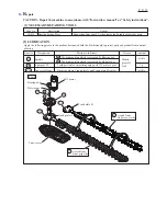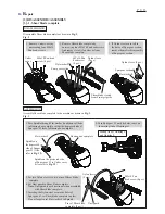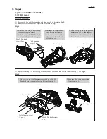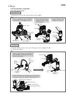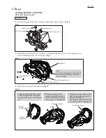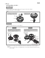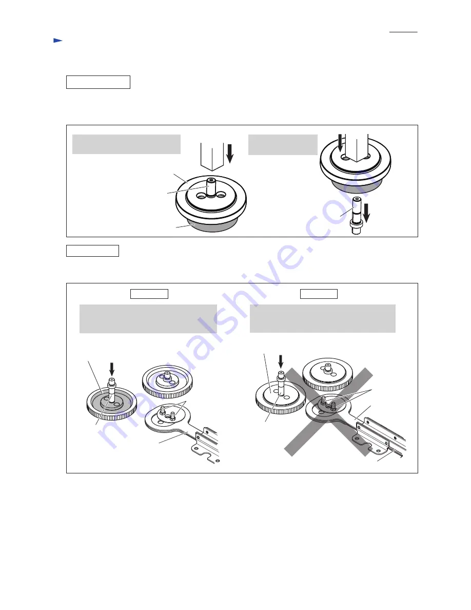
Fig. 11
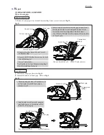
Fig. 12
[3] DISASSEMBLY/ASSEMBLY
[3] -3. Spur Gear 93
DISASSEMBLING
ASSEMBLING
(1) Assemble Spindle to Spur gear 93 as drawn in
Fig. 12
.
(2) Face its grooved side of Spur gear 93 to Bearing box complete and assemble Spur gear sesction to Bearing box
complete.
Note
: Be sure to set two Flat washers 8 on both Spindle ends, two Nylon sleeves into holes of Shear blade complete
as drawn in
Fig. 3
.
1R035
Do not insert Spindle from the projected side of
Spur gear 93 because Crank pin can not be fit to
Spur gear 93 precisely.
Press-fit Spindle from the depressed side of
Spur gear 93 so that Shear blade complete is
assembled to Spur gear 93 precisely.
CORRECT
WRONG
(1) Disassemble Shear blade complete, and then, remove Spur gear section as drawn in
Fig. 2
.
(2) Disassemble Spur gear 93 as drawn in
Fig. 11
.
Spindle
Spindle
Spur gear 93
1. Put Spur gear section on 1R035,
remove Spindle with Arbor press.
2. Spindle is removed
from Spur gear 93.
Crank pin
Spindle
Depressed side
of Spur gear 93
Projected side
of Spur gear 93
Spindle
Shear blade complete
Crank pin
Shear blade complete
Shear blade
complete
R
epair
P
7
/ 1
3


