
P 2 / 7
R
epair
[2] LUBRICATION
Put approx. 9g of Makita grease N No.1 in the gear room of Gear housing to protect parts and product from
unusual abrasion.
[3] DISASSEMBLY/ASSEMBLY
[1] NECESSARY REPAIRING TOOLS
CAUTION: Remove the drill bit from the machine for safety before repair/ maintenance !
Code No.
Description
Use for
1R269
Bearing Extractor
Removing Ball bearing
1R291
Retaining Ring S and R Pliers
Removing Ball bearing
1R316
Adjustable Bearing Retainer Wrench
Removing Bearing retainer
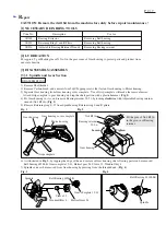
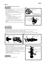
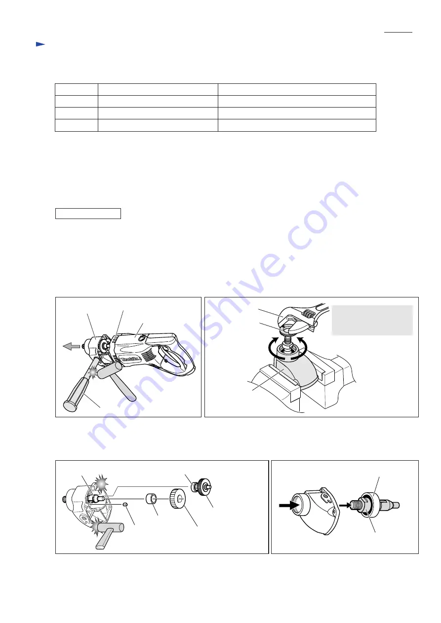
1) Remove Shaft holder.
2) Remove Carbon brush, and unscrew four 5x40 Tapping screws that fasten Gear housing to Motor housing.
3) Separate Gear housing from Gear housing cover complete. Use of Grip complete will make the removal easier.
Attach Grip complete to gear housing, and tap the shaft portion with a plastic hammer. (Fig. 1)
4) Fix Gear housing in vise, and remove Bearing retainer 22-36 by turning clockwise with Adjustable bearing retainer
wrench (No.1R316). (Fig. 2)
5) Remove Retaining ring S-15 from Spindle using Retainer ring S and R pliers.
[3] -1. Spindle and Gear Section
DISASSEMBLING
Motor housing
Grip complete
Gear housing
Gear housing cover complete
Fig. 1
Fig. 2
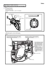
6) As illustrated in Fig. 3, by tapping the edge of the end surface of Gear housing, the following parts can be removed;
Ball bearing 607LLB, Gear complete 12-41, Helical gear 34, Sleeve 15, Woodruff key 4
7) Spindle can now be removed from Gear housing by pressing from the threaded end. (Fig. 4)
Fig. 3
Fig. 4
Woodruff Key 4
Sleeve 15
Ball Bearing 607LLB
Helical Gear 34
Gear Complete 12-41
Spindle
Spindle
Ball Bearing 6202LLB
Bearing retainer
22-36
No.1R316
Fit the pins of No.1R316
in the groove of Bearing
retainer.
Tighten
Loosen
Gear housing