


Model No.
Description
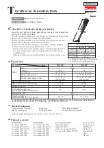
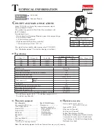
PRODUCT
C
ONCEPT AND MAIN APPLICATIONS
S
pecification
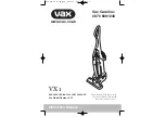
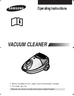
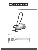
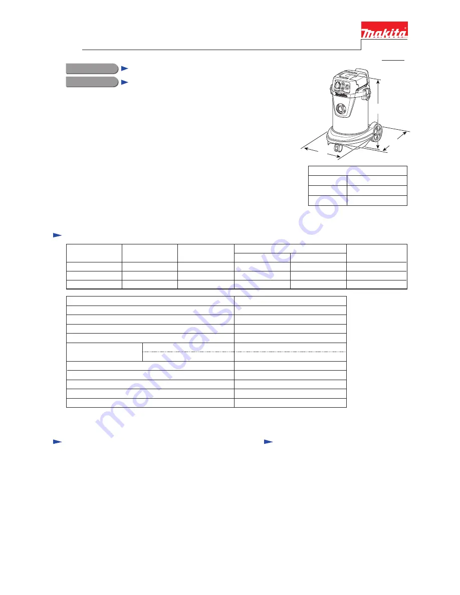
Dimensions: mm (")
Width (W)
Height (H)
Length (L)
552 (21-3/4)
398 (15-5/8)
685 (27)
VC3211M
Vacuum Cleaner
Model VC3211M is a Wet & Dry vacuum cleaner developed
based on Model VC3210L.
This product is approved for Dust Class M in accordance with
the EU standard.
Its main benefits are:
•
New automatic self-cleaning filtration system of our unique design
•
Power tool activation
*
•
32 Liter stainless steel tank
*
•
High maneuverability and easy mobility
*
*
The same advantage as Model VC3210L
P 1/
18
Continuous Rating (W)
Voltage (V)
Cycle (Hz)
Input
Output
Max. Output (W)
110
230
240
10.0
4.8
4.6
50/60
50/60
50/60
1,050
1,050
1,050
---
---
--
---
---
---
Current (A)
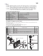
S
tandard equipment
Note:
The standard equipment for the tool shown above may vary by country.
O
ptional accessories
For
All models:
Hose complete 28-3.5 set .......... 1
(incl. Front cuff 38)
Front cuff 22 .............................. 1
Front cuff 24 .............................. 1
Belt hook
................................... 1
Hose band .................................. 1
Cap
............................................ 1
Poly bag 800x650 ...................... 1
Poly bag set
............................... 1
(incl. 10 pcs of Poly bag 800x650)
2.0
*
1
/ 3.5
*
2
22.0
Max. sealed suction: kPa
Max. air flow: m³/minute
Yes
Power tool activation
M
Dust class in accordance with the EU standard
Wet & Dry
Wet/Dry type
Yes
Variable suction power control by dial
Tank capacity: L
32
27
Weight according to EPTA-Procedure 01/2003
*
3
: kg (lbs)
*1
: with Hose complete 28-3.5
*2
: with Hose complete 38-2.5
*3
: with Poly bag 800x650
5.0 (16.4)
Power supply cord: m (ft)
Grounding
73
Noise: dB
16.9 (37.3)
Protection from electric shock
Dust
Water
Hose complete 28-2.5/ 28-3.5/
28-5.0/ 38-2.5/ 38-5.0
Front cuff 22/ 24/ 38
Filter bag set (5pcs/set)
Poly bag set (10 pcs/set)
Powder filter, Damper, Prefilter
Straight pipe, Bending pipe, Nozzle assembly,
Corner nozzle, Anchor nozzle, Round brush,
Cap, Cleaning set, Nozzle for wet application,
Belt hook, Hose band
W
H
This model is also available with cleaning set as VC3211MX1.
(See "Standard equipment" for what the cleaning set includes.)
For
VC3211MX1 only:
Cleaning set..................... 1
Includes one each of:
-Hose complete 38-2.5
-Straight pipe
-Bending pipe
-Nozzle assembly
-Corner nozzle
T
ECHNICAL INFORMATION
L