background image

Page 

15

 of 

36


5.2. Alarming the exceeding of the correct temperature range. 

The controller has the function of signaling the exceeding of the set temperature range. In order for 
the function to work properly, the appropriate temperature range must first be programmed, that 
is:  parameter  A1  –  temperature  below  which  the  alarm  will  be  activated,  and  parameter  A2  – 
temperature above which the alarm will be activated (see section 3.4.). 
The  third  parameter  to  be  defined  is  the  time  delay  of  switching  on  the  alarm  function  from  
the  moment  the  controller  is  switched  on  –  parameter  AA.  This  delay  eliminates  the  triggering  
of an alarm in the initial cooling phase. 
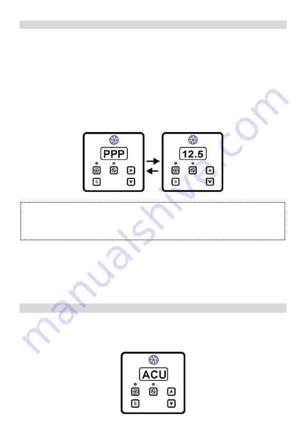
Exceeding  the  set  temperature  range  is  signaled  visually  and  audibly.  In  the  event  of  an  alarm,  
the buzzer is triggered cyclically every 1 min. for 5 sec., and alternately: PPP letters and temperature 
value are displayed.


ATTENTION 
The parameter AA is t

he same 

to the delay time specified in the function


of recording maximum 


and minimum temperature values. In other words, the delay value set in parameter  AA will be 
the same for recording maximum and minimum temperature and for parameters A1 and A2


The audible alarm can be turned off by setting the HE parameter to 1 (see section 3.4.). In this case, 
exceeding  the  set  temperature  range  is  signaled  only  visually,  as  shown  in  the  figure  above. 
The  alarm  system  (audible  and  visual)  can  also  be  turned  off  completely  by  changing  the  HA 
parameter to 1 (see section 3.4).


5.3. Temperature sensor damage indication. 

If the controller detects damage to the sensor, the letters ACU appear on the display and at the same 
time the audible alarm is activated. The operation of the chiller and the stirrer is interrupted until 
the failure is removed. 


Summary of Contents for MCH-07 v.3

Page 1: ...tally to activate the washing process during the cooling process The washing segment is activated only when the cooling is switched off The MCH 07 controller has a waterproof casing protection class I...

Page 2: ...ge 2 of 36 MCH 07 casing dimensions 177 x 126 x 56 mm MCH 07 f casing dimensions 206 x 140 x 56 mm power supply 230V AC 50 60 HZ protection class IP65 safety class CE basic version of MCH 07 controlle...

Page 3: ...Page 3 of 36 MCH 07 f variant with flange...

Page 4: ...PCB board with the bottom board After opening the casing disconnect this cable The cable is disconnected by removing the connector plug located in the bottom plate basic version of MCH 07 controller...

Page 5: ...Page 5 of 36 dimensioning for assembly MCH 07 f variant with flange connection diagram...

Page 6: ...al data of the cooling segment temperature measuring range from 40 0 OC to 120 0 OC control temperature range from 40 0 OC to 120 0 OC decreased by a set hysteresis measuring resolution of the tempera...

Page 7: ...1 2 Control function of the refrigeration system chiller depending on the measured temperature parameter C9 is set to 0 3 Light signaling function for switching on the cooling heating process blue di...

Page 8: ...ing of the voltage parameter dE 11 Real time clock 3 3 Programming for the cooling segment In order to ensure the correct cycle of the controller s operation it is necessary to program its operating p...

Page 9: ...nction symbol range of the settings factory setting entry in the setting mode UC0 access code 1 2 controller operation mode C9 0 cooling mode 1 heating mode 0 limitation of the lower value for the con...

Page 10: ...dstill of the chiller unit the stirrer works according to times set in E1 and E2 2 unavailable3 3 unavailable 3 4 continuous operation independent of the chiller operation and times set in E1 and E2 1...

Page 11: ...y settings and the function value is reset to 0 0 exit from the setting mode EE 1 Adjustments must be made so that the condition b1 b2 is always met The values of parameters b1 and b2 are not control...

Page 12: ...e cooling temperature in the range of 40 OC up to 120 OC In order to limit the range of control so as to prevent the user of the refrigeration device from setting the temperature outside this range th...

Page 13: ...ing of the stirrer operation red diode 4 2 2 Manually triggered operation of the stirrer The manual stirrer operation can be initiated by pressing the button marked with the symbol seesection 3 at thi...

Page 14: ...ure values are stored in the controller s memory The programmable delay time of this function allows not to take into account the maximum temperature when the controller is started and thus to pre coo...

Page 15: ...ggered cyclically every 1 min for 5 sec and alternately PPP letters and temperature value are displayed ATTENTION The parameter AA is the same to the delay time specified in the function of recording...

Page 16: ...ducer after voltage decay Controller has the ability to protect the chiller and motoreducer in the event of momentary decays and the appearance of the supply voltage this is done by setting the dE par...

Page 17: ...n MCH 07 MCH 07T1 version with the possibility of water heating control and thermostatic control equipped with one sensor common with the cooling segment MCH 07T2 version with the possibility of water...

Page 18: ...hydrostatic in MCH 07T version it is possible to set the controller to indicate the current temperature measured by the temperature sensor LED diodes marked with numbers 1 8 indicating which relays ar...

Page 19: ...230 VAC supply voltage switching voltage input for relay 5 any of the range from 6V to 380V which can be different from the voltage connected to relays 1 4 and 6 8 input for hydrostatic connection in...

Page 20: ...ings made the program execution remains off or starts in the same place where it was stopped You can limit the return time in the settings of this function for interrupted operation after voltage deca...

Page 21: ...isplay shows the time to complete the entire program The time indicated by the display does not take into account the time of pouring water when using a hydrostatic as well as the time needed to heat...

Page 22: ...s possible in the range of 10 OC every 0 5 OC where 0 5 OC is indicated by lighting up a dot by digit of temperature Corrections of the readings should be made only after the actual confirmation of fa...

Page 23: ...ight to left on the display to edit the duration of the step switching between diodes to determine the relay status signaled by a diode entering the settings related to temperature functions MCH 07T v...

Page 24: ...9 59 min 01 00 min setting the maximum power supply decay time after which the program will be resumed UAP 0 no time limit the program will be always resumed after the power supply is restored 1 time...

Page 25: ...only if PUL5 1 PHo setting the time for which relay 7 will be inactive from 1 sec to 59 sec 1 s 6 7 Selection and setting of the example function The following is a graphical representation of the ch...

Page 26: ...nce in the case of a step with a hydrostatic active this is a protection in the event of a mechanical suspension of the hydrostatic Additionally for the MCH 07T version optionally you can assign to an...

Page 27: ...modified program beforehand For convenience the table should look similar to the tables of the factory programs It should be remembered that after 30 sec without any related activities with programmi...

Page 28: ...ection by pressing the S button and change the value of this parameter from 0 to 1 using the button Then confirm the changes by pressing the S button again After doing this disconnect the power supply...

Page 29: ...lock it indicates that the battery is running low It should be replaced alone or sent to a service center for payable replacement 7 2 Choosing the washing program At any time the user can read which w...

Page 30: ...instead of time This function can only be assigned to one or more steps and in the remaining steps the time to finish the washing process can still be displayed Starting the washing process is also si...

Page 31: ...lay output no 3 made by the installer either the vacuum pump PP or the stirrer PPR can be switched on manually Switching off occurs by pressing the button again or automatically after the time set by...

Page 32: ...er relay ZW cold water relay PP vacuum pump relay PML milk pump relay PM washing pump relay PPR stirrer relay ZZ dump valve relay H hydrostatic ZD1 detergent dispensing valve 1 relay w free ZD2 deterg...

Page 33: ...f pouring water with the hydrostatic switched on it is not necessary to know the time needed to pour water PRO2 WASHING A MILKING DEVICE diode no 1 2 3 4 5 6 7 8 9 comments relay no 1 2 3 4 5 6 7 8 mo...

Page 34: ...12 15 00 1 1 max time 13 05 00 1 1 14 00 30 1 1 1 total time 27 20 total time does not take into account the time of pouring water with the hydrostatic switched on it is not necessary to know the time...

Page 35: ...uring water with the hydrostatic switched on it is not necessary to know the time needed to pour water PRO2 WASHING A MILKING DEVICE diode no 1 2 3 4 5 6 7 8 H comments relay no 1 2 3 4 5 6 7 8 mode s...

Page 36: ...4 05 00 1 1 15 00 30 1 1 1 total time 27 20 total time does not take into account the time of pouring water with the hydrostatic switched on it is not necessary to know the time needed to pour water P...

Reviews: