5
ENGLISH
(Original instructions)
Explanation of general view
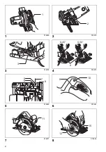
1
Lever
2
Front lever
3
Rear wing nut
4
Stopper
5
0° position
6
45° position
7
Cutting line
8
Screw
9
Switch trigger
10 Lock-off button
11 Light
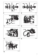
12 Hex wrench
13 Loosen
14 Tighten
15 Shaft lock
16 Mounting shaft
17 Inner flange
18 Saw blade
19 Outer flange
20 Hex bolt
21 Ring
22 Dust nozzle
23 Vacuum cleaner
24 Hose
25 Clamp lever
26 Rip fence (Guide rule)
27 Adjusting screw for 0°
28 Adjusting screw for 45°
29 Triangular rule
30 Base
31 Limit mark
32 Screwdriver
33 Brush holder cap
SPECIFICATIONS
• Due to our continuing program of research and devel-
opment, the specifications herein are subject to change
without notice.
• Specifications may differ from country to country.
• Weight according to EPTA-Procedure 01/2003
ENE078-1
Intended use
The tool is intended for performing lengthways and
crossways straight cuts and mitre cuts with angles in
wood while in firm contact with the workpiece. With
appropriate saw blades, aluminum can also be sawed.
ENF100-1
For public low-voltage distribution systems of
between 220 V and 250 V
Switching operations of electric apparatus cause voltage
fluctuations. The operation of this device under unfavor-
able mains conditions can have adverse effects to the
operation of other equipment. With a mains impedance
equal or less than 0.32 Ohms it can be presumed that
there will be no negative effects.
The mains socket used for this device must be protected
with a fuse or protective circuit breaker having slow trip-
ping characteristics.
GEA010-1
General Power Tool Safety Warnings
WARNING Read all safety warnings and all
instructions.
Failure to follow the warnings and instruc-
tions may result in electric shock, fire and/or serious
injury.
Save all warnings and instructions for future reference.
GEB013-6
CIRCULAR SAW SAFETY WARNINGS
Cutting procedures
1.
DANGER: Keep hands away from cutting
area and the blade. Keep your second hand on
auxiliary handle, or motor housing.
If both hands
are holding the saw, they cannot be cut by the blade.
2.
Do not reach underneath the workpiece.
The
guard cannot protect you from the blade below the
workpiece.
3.
Adjust the cutting depth to the thickness of the
workpiece.
Less than a full tooth of the blade teeth
should be visible below the workpiece.
4.
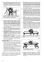
Never hold piece being cut in your hands or
across your leg. Secure the workpiece to a
stable platform.
It is important to support the work
properly to minimize body exposure, blade binding,
or loss of control.
000157
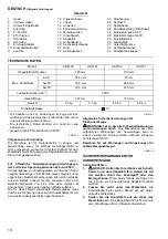
Model
HS6100
HS6101
HS7100
HS7101
Blade diameter
165 mm
190 mm
Max. cutting depth
at 0°
54.5 mm
67 mm
at 45°
39.5 mm
48.5 mm
at 50°
35.5 mm
43.5 mm
No load speed (min
–1
)
5,500
Overall length
297 mm
310 mm
Net weight
3.7 kg
3.7 kg
4.0 kg
4.0 kg
Safety class
/II
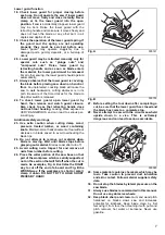
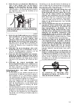
A typical illustration of proper hand support,
workpiece support, and supply cord routing (if
applicable).
Summary of Contents for HS7100
Page 59: ...59 4 000157 5 6 7 8 9 10 11 12 T 000154 000156...
Page 60: ...60 13 o 14 15 16 000194 17 18 19 20 21 22 23 24 25 26 A B 000147 A...
Page 62: ...62 8 15 88 9 15 88 10 a a 11 12 13 14 Makita 15 16...
Page 71: ...71...
Page 72: ...Makita Corporation Anjo Aichi Japan www makita com 885084 994 IDE...
Page 73: ...McGrp Ru McGrp Ru...


