8
33. Wear a dust mask and hearing protection when
use the tool.
SAVE THESE INSTRUCTIONS.
WARNING:
DO NOT let comfort or familiarity with product
(gained from repeated use) replace strict adherence
to safety rules for the subject product. MISUSE or
failure to follow the safety rules stated in this instruc-
tion manual may cause serious personal injury.
FUNCTIONAL DESCRIPTION
CAUTION:
• Always be sure that the tool is switched off and
unplugged before adjusting or checking function on the
tool.
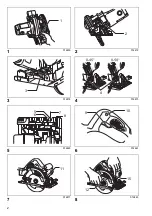
Adjusting depth of cut (Fig. 1)
CAUTION:
• After adjusting the depth of cut, always tighten the lever
securely.
Loosen the lever on the depth guide and move the base
up or down. At the desired depth of cut, secure the base
by tightening the lever.
For cleaner, safer cuts, set cut depth so that no more
than one blade tooth projects below workpiece. Using
proper cut depth helps to reduce potential for dangerous
KICKBACKS which can cause personal injury.
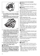
Bevel cutting (Fig. 2, 3 & 4)
Loosen the front lever and rear wing nut. Set for the
desired angle (0° – 50°) by tilting accordingly, then
tighten the lever and wing nut securely.
Use the 45° stopper when you do precise 45° angle cut-
ting. Turn the stopper clockwise fully for bevel cut (0° –
45°) and turn it counterclockwise for 0° – 50° bevel cuts.
Sighting (Fig. 5)
For straight cuts, align the 0° position on the front of the
base with your cutting line. For 45° bevel cuts, align the
45° position with it. The position of the top guide is
adjustable.
Switch action (Fig. 6)
CAUTION:
• Before plugging in the tool, always check to see that
the switch trigger actuates properly and returns to the
“OFF” position when released.
To prevent the switch trigger from being accidentally
pulled, a lock-off button is provided. To start the tool,
push in the lock-off button and pull the switch trigger.
Release the switch trigger to stop.
Do not pull the switch lever hard without pulling the lock-
off lever. This can cause switch breakage.
For Model HS6101, HS7101
Lighting the lamp (Fig. 7)
CAUTION:
• Do not look in the light or see the source of light
directly.
The lamp lights up when the tool is plugged. The lamp
keeps on lighting until the tool is unplugged.
NOTE:
• Use a dry cloth to wipe the dirt off the lens of lamp. Be
careful not to scratch the lens of lamp, or it may lower
the illumination.
• Do not use gasoline, thinner or the like to clean the lens
of lamp. Using such substances will damage the lens.
ASSEMBLY
CAUTION:
• Always be sure that the tool is switched off and
unplugged before carrying out any work on the tool.
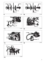
Removing or installing saw blade (Fig. 8)
CAUTION:
• Be sure the blade is installed with teeth pointing up at
the front of the tool.
• Use only the Makita wrench to install or remove the
blade.
To remove the blade, press the shaft lock so that the
blade cannot revolve and use the hex wrench to loosen
the hex bolt counterclockwise. Then remove the hex bolt,
outer flange and blade.
For tool with the inner flange for a 15.88 mm hole-
diameter saw blade (Fig. 9)
Mount the inner flange with its recessed side facing out-
ward onto the mounting shaft and then place saw blade,
outer flange and hex bolt.
BE SURE TO TIGHTEN THE HEX BOLT CLOCKWISE
SECURELY.
For tool with the inner flange for other than 15.88 mm
hole-diameter saw blade (Fig. 10)
The inner flange has a certain diameter protrusion on
one side of it and a different diameter protrusion on the
other side. Choose a correct side on which protrusion fits
into the saw blade hole perfectly.
Next, mount the inner flange onto the mounting shaft so
that the correct side of protrusion on the inner flange
faces outward and then place saw blade and outer
flange.
BE SURE TO TIGHTEN THE HEX BOLT CLOCKWISE
SECURELY.
CAUTION:
•
Make sure that the protrusion “a” on the inner
flange that is positioned outside fits into the saw
blade hole “a” perfectly.
Mounting the blade on the
wrong side can result in the dangerous vibration.
When changing blade, make sure to also clean upper
and lower blade guards of accumulated sawdust. Such
efforts do not, however, replace the need to check lower
guard operation before each use.
(Fig. 11)
Hex wrench storage (Fig. 12)
When not in use, store the hex wrench as shown in the
figure to keep it from being lost.
Connecting a vacuum cleaner (Fig. 13 & 14)
When you wish to perform clean cutting operation, con-
nect a Makita vacuum cleaner to your tool. Install the
dust nozzle on the tool using the screw. Then connect a
hose of the vacuum cleaner to the dust nozzle as shown
in the figure.
Summary of Contents for HS7100
Page 59: ...59 4 000157 5 6 7 8 9 10 11 12 T 000154 000156...
Page 60: ...60 13 o 14 15 16 000194 17 18 19 20 21 22 23 24 25 26 A B 000147 A...
Page 62: ...62 8 15 88 9 15 88 10 a a 11 12 13 14 Makita 15 16...
Page 71: ...71...
Page 72: ...Makita Corporation Anjo Aichi Japan www makita com 885084 994 IDE...
Page 73: ...McGrp Ru McGrp Ru...


