[3] DISASSEMBLY/ASSEMBLY
[3]-3. Blade case complete, Safety cover
DISASSEMBLING
ASSEMBLING
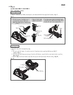
Fig. 11
Fig. 12
M5x16 Pan head screws
Unscrew M5x16 Pan head screws, then remove Bearing box from Blade case.
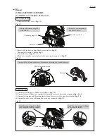
1) Disassemble Safety cover. (
Fig. 11
)
Tension spring 4
Safety cover
Retaining ring S-38
1. Remove Retaining ring S-38
with 1R003.
2) Remove Motor housing from Blade case complete. (
Fig. 8
)
Then pull off Armature. (
left
in
Fig. 9)
3) Dismantle Base. (
Figs. 3
,
4
,
5
)
4) Blade case complete can be replaced after removing Bearing box. (
Fig. 12
)
(1) Assemble Bearing box to Blade case complete. (
Fig. 12
)
(2) Assemble Base to Blade case complete by doing the reverse of the steps described in
Figs. 5, 4, 3
.
(3) Assemble Armature and Motor housing by doing the reverse of the steps described in
Figs. 9
,
8
.
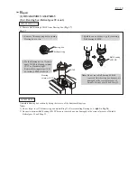
(4) Assemble Safety cover to Bearing box section as instructed in
Fig. 13
.
Bearing box
Fig. 13
Hook Tension spring 4 to Blade
cover from the inside.
Hook Tension spring 4 to Blade
case complete from the outside.
2. Remove Tension spring 4
and Safety cover.
Tension spring 4
P
7
/
1
0
R
epair


