
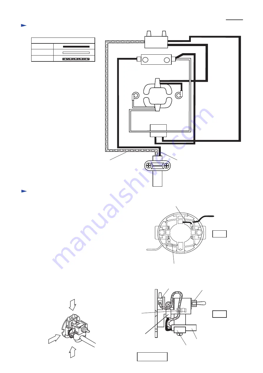
C
ircuit diagram
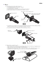
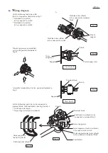
W
iring diagram
Color index of lead wires
Black
White
Blue
Power supply cord
Switch
Field
1
2
Terminal
block
Noise suppressor
Blue or white
Black or brown
The following lead wires have to be passed
outside of the lead wires to be connected to
brush holder, respectively.
* Field lead wire (white) to be connected to switch
* Field lead wire (black) to be connected to terminal
block
The insulated terminals have to be
connected with switch terminals as
illustrated in Fig. B.
Fix the lead wire (blue or white) of power supply cord,
with lead holder as illustrated in Fig. B.
Field lead wire (white)
to be connected to switch
Field lead wire (black)
to be connected to
terminal block
Lead wires (white) to be
connected to brush holder
Lead wires (black) to be
connected to brush holder
Power supply cord
Strain relief
Terminal block
Switch
Insulated
terminal connected
with switch terminal
Fig. A
Fig. B
Lead holder
A
B
C
View from A
P
4
/
5