
W
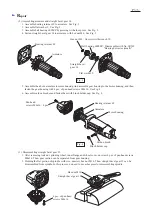
iring diagram
Field lead wire (white)
to be connected to switch
Fix the following lead wires with
the slit of support as illustrated in Fig. C.
* Field lead wire (white)
to be connected to switch
* Field lead wire (white)
to be connected to switch
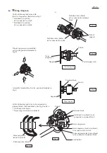
If noise suppressor is assembled,
set it in the position illustrated in
Fig. D.
Assemble terminal block to the position illustrated in
Fig. E.
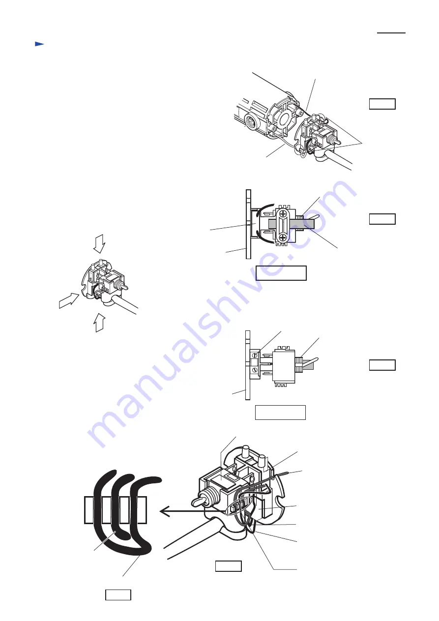
Fix the following lead wires to be connected to
terminal block, with lead holder. See Fig.F and F-1.
* Field lead wire (black)
* Noise suppressor lead wire (black)
Field lead wire (black)
to be connected to terminal
block
Fig. C
Fig. D
Fig. E
Fig. F
Slits of
support
A
B
C
View from B
View from C
Field lead wire (black) to be
connected to terminal block
Noise suppressor lead wire (black)
to be connected to terminal block
Noise suppressor lead wire (black)
to be connected to switch
Noise
suppressor
Power supply cord
Switch
Switch
Terminal block
Support
Support
Terminal block
Switch
Noise suppressor
Lead holder
Noise suppressor
lead wire (black)
Fig. F-1
Field lead wire (black)
P
5
/
5