www.malags.com
15
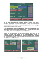
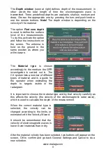
some test measurements prior the 3D Project. This can be done by 2-3
single parallel profiles giving an indication of how the objects are situated.
See Fig. 3.2.
Grid
-ma
t
Grid
-ma
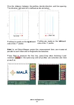
t
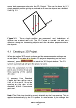
Figure 3.2
Three single profiles are measured, and indications of
objects are marked with red. The 3D Project is carried out with one
direction along the interesting objects and one direction perpendicular to
the objects.
4.1 Creating a 3D Project
When the option 3D Project is chose and the measurements settings are
made (Note! Point interval is fixed in 3D projects depending on the used
antenna), press
to reach the 3D Project window. The CX
system automatically will give the project a name.
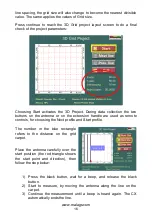
Here the parameters for the
grid is set, in terms of size and
lines spacing of the wanted
3D cube.
If pressing Use Standard
Carpet the size will be set to
0.80 x 0.8 m and 0.10 cm line
spacing as the size of the
standard MALÅ Geoscience
grid-mat.
Note!
The Grid size should be evenly divisible by the Line spacing. This is
applied automatically by the CX system. In other words, if you change the

