www.malags.com
40
used in another measurement direction, for instance to investigate
polarization effects.
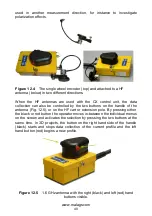
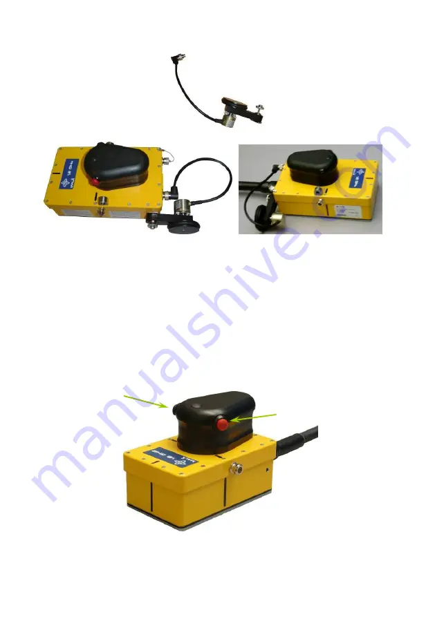
Figure 12.4
The single wheel encoder (top) and attached to a HF
antenna (below) in two different directions.
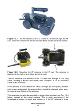
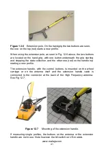
When the HF antennas are used with the CX control unit, the data
collection can also be controlled by the two buttons on the handle of the
antenna (Fig. 12.5), or on the HF cart or extension pole. By pressing either
the black or red button the operator moves in-between the individual menus
on the screen and activates the selection by pressing the two buttons at the
same time.
In 3D projects, the button on the right hand side of the handle
(black) starts and stops data collection of the current profile and the left
hand button (red) begins a new profile.
Figure 12.5
1.6 GHz antenna with the right (black) and left (red) hand
buttons visible.

