www.malags.com
41
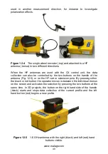
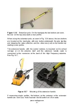
Figure 12.6
Extension pole. On the handgrip the two buttons are seen,
the one on the top (red) starts a new profile.
When using the extension pole, as seen in Fig. 12.6 above, the two buttons
are located on the hand grip, with one button underneath the grip starting
and stopping the data collection, and the other one (red) on the handle top
starting a new profile.
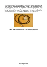
The extension handle, with the control buttons, is mounted on the wheel
carriage or on the antenna itself and the extension handle cable is
connected to the connector at the back of the High Frequency antenna.
See Fig 12.7.
Figure 12.7
Mounting of the extension handle.
If measuring single profiles, the buttons on the antenna or the extension
handle are not in use. Note however the kill-switch on US-models.


