3
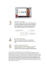
Develop a survey grid
Develop a survey grid based on the estimated alignment of
the utility. Set perpendicular survey line to be traversed and
used to determine the precise lateral location of the utility
and its longitudinal extent. Also set several parallel survey
lines to determine the presents of any lateral services.
4
Survey the target area
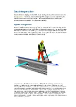
Mark out the target site using the survey grid and pro-
gressively traverse the perpendicular and parallel survey
lines.
5
Mark the location of the utility
While traversing the perpendicular survey lines, search for
the begin of a feature
signature
1
. When the signature
appears, continue moving the MALÅ Easy Locator HDR cart
1
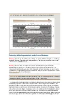
A representation of the reflected radar signal in a GPR profile. Reflected signals are caused by
changes in the dielectric properties of the target medium. These dielectric differences are usual
caused by differences in materials, e.g., a buried object or reinforcing in concrete. Objects of a discrete
length are generally characterized by a hyperbolic reflection in the GPR profile, and are referred to as
point source reflections. A linear object, such as a pipe, will also display the characteristics of a dis-
crete-length object if the GPR scan is performed perpendicular to its longitudinal alignment, and are
referred to as planar reflections. As the scan is moved towards the longitudinal alignment of the linear
object, the hyperbolic refection flattens until it approaches a horizontal line in the GPR profile. The
shape of the signature is also affected by many other factors, including the size of the object, the signal
velocity, and the object material.

