Hyperbola Fitting
Hyperbola fitting
is a standard procedure for estimating the average velocity of the
GPR signal for
point source reflections
1
. These point source reflections are typically
displayed as a hyperbola in the GPR profile. Different ground conditions (dielectric prop-
erties) affect the signal velocity and the resulting shape of the hyperbolic
signature
2
in
the GPR profile. Dry sandy soils allow the signal to propagate easily resulting in a higher
signal velocity and flatter hyperbola compared to wet clay where the wave propagation is
much slower. Using this phenomenon, it is possible to estimate the signal velocity in the
ground by comparing and fitting the shape of the measured hyperbola to that of pub-
lished hyperbola shape verses signal velocity data. Once the signal velocity has been
determined, it is possible to estimate the depth to the object causing the signature.
Warning:
The user must ensure that the scan is accurately aligned at 90 degrees to the line of
the utility. Any increase in the angle of the scan from the perpendicular will cause the shape of
the hyperbola to broaden and result in an overestimation of the signal velocity.
1
Start a GPR scan
Use the procedure described in the
section
to conduct a GPR scan across the area where a utility is loc-
ated.
2
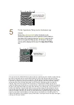
Position the MALÅ Easy Locator HDR over the
utility
After the full extent of the feature
signature
3
has been dis-
played on the monitor screen, reverse the MALÅ Easy Loc-
ator HDR cart until the
Vertical position cursor
is aligned
with the center of the hyperbola.
1
Reflections which often appear as hyperbolas in GPR profiles. They are commonly generated from
distinct, spatially-restricted, non-planar features (‘point targets’), such as rocks, metal objects, walls,
tunnels, voids, and pipes crossed at right angles to the GPR scan.
2
A representation of the reflected radar signal in a GPR profile. Reflected signals are caused by
changes in the dielectric properties of the target medium. These dielectric differences are usual
caused by differences in materials, e.g., a buried object or reinforcing in concrete. Objects of a discrete
length are generally characterized by a hyperbolic reflection in the GPR profile, and are referred to as
point source reflections. A linear object, such as a pipe, will also display the characteristics of a dis-
crete-length object if the GPR scan is performed perpendicular to its longitudinal alignment, and are
referred to as planar reflections. As the scan is moved towards the longitudinal alignment of the linear
object, the hyperbolic refection flattens until it approaches a horizontal line in the GPR profile. The
shape of the signature is also affected by many other factors, including the size of the object, the signal
velocity, and the object material.
3
A representation of the reflected radar signal in a GPR profile. Reflected signals are caused by
changes in the dielectric properties of the target medium. These dielectric differences are usual
caused by differences in materials, e.g., a buried object or reinforcing in concrete. Objects of a discrete
length are generally characterized by a hyperbolic reflection in the GPR profile, and are referred to as
point source reflections. A linear object, such as a pipe, will also display the characteristics of a dis-
crete-length object if the GPR scan is performed perpendicular to its longitudinal alignment, and are
referred to as planar reflections. As the scan is moved towards the longitudinal alignment of the linear
object, the hyperbolic refection flattens until it approaches a horizontal line in the GPR profile. The
shape of the signature is also affected by many other factors, including the size of the object, the signal
velocity, and the object material.

