1
S W I T C H E S
CHECKING PROCEDURES
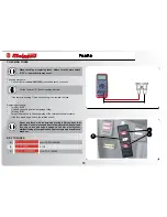
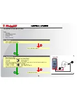
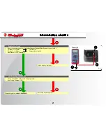
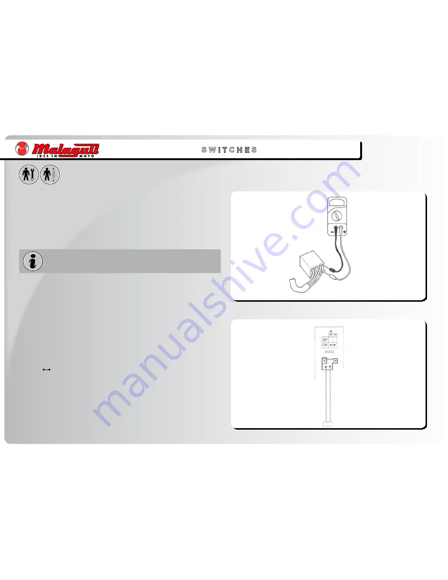
Using a Tester (
Code n°081100
), check the switches by making sure that there is
continuity between terminals and that they are correctly connected.
Replace the switch, even if only one of the possible combinations does not give the
requested result.
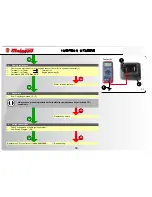
Select “Ω” (ohm) function of tester; sound-emitting function.
Using the tester in “Ω” mode, you can also check integrity of the lamps and lamp
sockets.
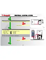
CONNECTION OF THE SWITCHES DESCRIBED IN THIS MANUAL
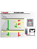
This manual contains connection diagrams, like the one illustrated hereby, which
illustrate how switch terminals should be connected (key switch, brake switch,
MODE
button, etc.).
The first column from the left indicates the different positions of the switches; the
top line indicates the colour of the wires connected to the switch terminals.
The “
” symbol identifies terminals in which there is a condition of continuity, i.e.
a closed circuit, in a certain position of the switch.
In this diagram:
“
BL-B
” and “
R
”: there is continuous contact when the switch is “
ON
”.
•
•
•
•
Summary of Contents for Centro 50 4T
Page 1: ......


