8
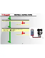
OK
NO
OK
NO
NO
OK
1
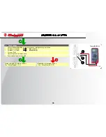
Tester (DC 0 v)
5
4
3
2
1
M/N B AZ N GL
F. 24
5
4
3
2
1
M/N B AZ N GL
F. 25
A
S I G N A L L I N G S Y S T E M
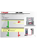
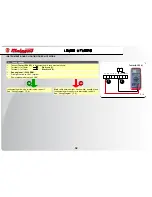
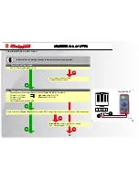
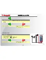
4. Check regulator
Connector
(A)
detached.
Provide a jumper between
Brown/Black
cable (PIN 5) and
Light blue
cable (PIN 3).
Turn key “
ON
”.
Operate right/left turn indicator switch to make sure that indicators come on and remain steadily lit.
•
•
•
•
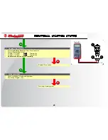
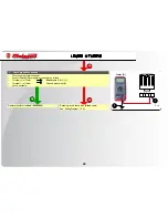
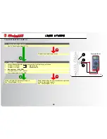
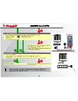
. Check voltage (Test “B”)
Keep connector detached from regulator and connect
Tester (0 v DC),
as follows:
Terminal (+) of Tester
Light blue
cable -PIN 3-
(1)
.
Terminal (-) of Tester
Chassis grounding
()
.
Turn key “
ON
”.
Power measured must be
>
1 v
.
•
•
•
•
•
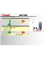
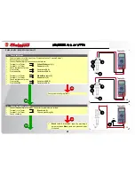
Light blue
cable between key switch and regulator
connector (PIN 3) is interrupted: repair it.
See “Wiring Diagram” (P. 8).
Always check continuity of Black cable (PIN ) and
chassis ground connection.
Replace voltage regulator.
Repeat all checks from the beginning (tests have not been
performed correctly).
If ground connection (pin ) or power supply (pin ) are lacking, the regulator will
cause malfunctioning of the lighting circuit and battery recharging system, as well as
disengagement of the carburettor “starter”.
Summary of Contents for Centro 50 4T
Page 1: ......

