40
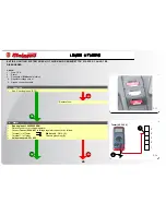
NO
1
NO
OK
OK
OK
1
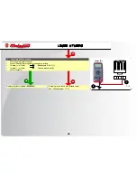
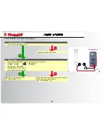
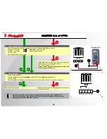
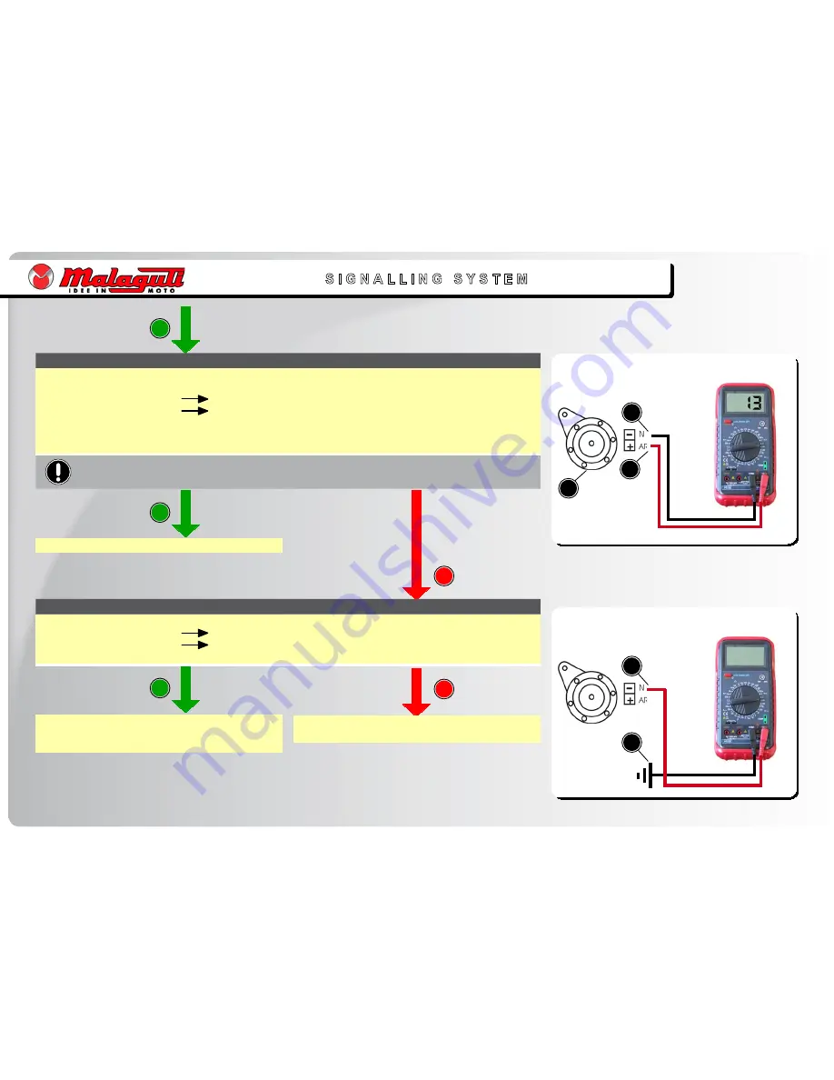
Tester (DC 0 v)
F. 27
F. 28
S I G N A L L I N G S Y S T E M
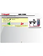
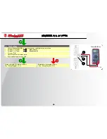
4. Check ground connection.
Connect
Tester (Ω)
as follows:
Terminal (+) of Tester
Black
cable
(1)
.
Terminal (-) of Tester
Chassis grounding
()
.
Check continuity.
•
•
•
•
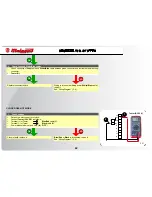
Orange
cable between left hand switch and horn is
interrupted: repair it.
See “Wiring Diagram” (P. 8).
Black
cable is interrupted: repair it.
See “Wiring Diagram” (P. 8).
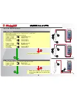
Tester (
Ω
)
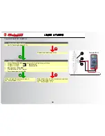
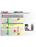
. Horn
Disconnect horn cables
()
.
Connect
Tester (DC 0 v)
to terminals, as follows:
Terminal (+) of Tester
Orange
cable
(1)
.
Terminal (-) of Tester
Black
cable
()
.
Turn key “
ON
”.
Press “
HORN
” button.
Power measured must be
>
1 v
.
•
•
•
•
•
•
•
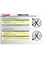
Never invert position of cables.
Replace horn.
Summary of Contents for Centro 50 4T
Page 1: ......

