61
11/00
F18 - 125
F18 - 125
F18 - 125
F18 - 125
F18 - 125cc / 150cc
cc / 150cc
cc / 150cc
cc / 150cc
cc / 150cc
LUZ FARO POSTERIOR NO SE
LUZ FARO POSTERIOR NO SE
LUZ FARO POSTERIOR NO SE
LUZ FARO POSTERIOR NO SE
LUZ FARO POSTERIOR NO SE
ENCIENDE
ENCIENDE
ENCIENDE
ENCIENDE
ENCIENDE
A)
A)
A)
A)
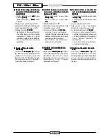
A) Controlar la lámpara y el
Controlar la lámpara y el
Controlar la lámpara y el
Controlar la lámpara y el
Controlar la lámpara y el
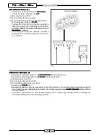
portalámpara (F. 40)
portalámpara (F. 40)
portalámpara (F. 40)
portalámpara (F. 40)
portalámpara (F. 40)
B)
B)
B)
B)
B) Controlar la tensión (tester DC
Controlar la tensión (tester DC
Controlar la tensión (tester DC
Controlar la tensión (tester DC
Controlar la tensión (tester DC
20V) al conector del cableo
20V) al conector del cableo
20V) al conector del cableo
20V) al conector del cableo
20V) al conector del cableo
posterior.
posterior.
posterior.
posterior.
posterior.
- Terminal (+) tester: terminal cable
rosa
rosa
rosa
rosa
rosa
- Terminal (-) tester: terminal cable
negro
negro
negro
negro
negro
• Llave conmutador en “ON”.
• Situar el interruptor luces derecho
en
.
• La tensión debe ser de 12 volt.
12 volt.
12 volt.
12 volt.
12 volt.
-
Como valor especificado: el
circuito del cableo principal
funciona. Cableo faro trasero
defectuoso
→
sustituir o
reparar.
-
Fuera del valor especificado:
continuar la búsqueda.
C)
C)
C)
C)
C) Control interruptor luces del con-
Control interruptor luces del con-
Control interruptor luces del con-
Control interruptor luces del con-
Control interruptor luces del con-
mutador derecho
mutador derecho
mutador derecho
mutador derecho
mutador derecho
• Ver pág 56 (“Iluminación salpicade-
ro” punto “A”)
-
No hay continuidad: sustituir el
conmutador derecho
-
Hay continuidad: continuar la
búsqueda.
D)
D)
D)
D)
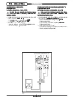
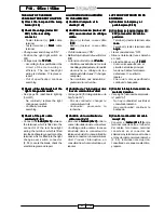
D) Control continuidad del cable
Control continuidad del cable
Control continuidad del cable
Control continuidad del cable
Control continuidad del cable
rosa
rosa
rosa
rosa
rosa (F. 41)
(F. 41)
(F. 41)
(F. 41)
(F. 41)
• Conectar el tester (
tester (
tester (
tester (
tester (
Ω
Ω
Ω
Ω
Ω
x 1)
x 1)
x 1)
x 1)
x 1) entre
terminal conectado en el conector
del cableo faro trasero, terminal
conectado en el conector del
salpicadero y terminal conecta-do en
el conector del conmutador derecho
(F. 55). Individuar inter-rupción,
consultando el esquema eléctrico,
y reparar.
LA LUMIERE DU FEU ARRIÈRE
LA LUMIERE DU FEU ARRIÈRE
LA LUMIERE DU FEU ARRIÈRE
LA LUMIERE DU FEU ARRIÈRE
LA LUMIERE DU FEU ARRIÈRE
NE S’ALLUME PAS
NE S’ALLUME PAS
NE S’ALLUME PAS
NE S’ALLUME PAS
NE S’ALLUME PAS
A)
A)
A)
A)
A) Contrôler l’ampoule et la
Contrôler l’ampoule et la
Contrôler l’ampoule et la
Contrôler l’ampoule et la
Contrôler l’ampoule et la
douille (F. 40)
douille (F. 40)
douille (F. 40)
douille (F. 40)
douille (F. 40)
B)
B)
B)
B)
B) Contrôler la tension (testeur CC
Contrôler la tension (testeur CC
Contrôler la tension (testeur CC
Contrôler la tension (testeur CC
Contrôler la tension (testeur CC
20V) au connecteur du câblage
20V) au connecteur du câblage
20V) au connecteur du câblage
20V) au connecteur du câblage
20V) au connecteur du câblage
arrière
arrière
arrière
arrière
arrière
- Borne (+) testeur : cosse câble
rose
rose
rose
rose
rose
- Borne (-) testeur : cosse câble
noir
noir
noir
noir
noir
• Clef démarreur sur “ON”.
• Mettre l’interrupteur du feux droit sur
.
• La tension droit être de 12 volts.
12 volts.
12 volts.
12 volts.
12 volts.
- Conforme aux indications : le circuit
du câblage principal est en bon état
de marche. Le câblage du feu
arrière est défectueux
→
changer
ou réparer.
- Non conforme aux indications :
poursuivre la recherche.
C)
C)
C)
C)
C) Contrôle de l’interrupteur des
Contrôle de l’interrupteur des
Contrôle de l’interrupteur des
Contrôle de l’interrupteur des
Contrôle de l’interrupteur des
feux du commutateur droit
feux du commutateur droit
feux du commutateur droit
feux du commutateur droit
feux du commutateur droit
• Voir page 56 (“Eclairage tableau de
bord” point “A”)
- Pas de continuité : changer le
commutateur droit
- Continuité
: poursuivre la
recherche.
D)
D)
D)
D)
D) Contrôle de la continuité du
Contrôle de la continuité du
Contrôle de la continuité du
Contrôle de la continuité du
Contrôle de la continuité du
câble rose
câble rose
câble rose
câble rose
câble rose (F. 41)
(F. 41)
(F. 41)
(F. 41)
(F. 41)
• Brancher le testeur (
testeur (
testeur (
testeur (
testeur (
Ω
Ω
Ω
Ω
Ω
x 1)
x 1)
x 1)
x 1)
x 1) entre la
cosse introduite dans le connecteur
du câblage du feu arrière, la cosse
introduite dans le connecteur du
tableau de bord et la cosse introduite
dans le connecteur du commutateur
droit. Trouver l’interruption, en
consultant le schéma électrique, et
réparer.
THE LIGHT OF THE REAR
THE LIGHT OF THE REAR
THE LIGHT OF THE REAR
THE LIGHT OF THE REAR
THE LIGHT OF THE REAR
HEADLIGHT DOES NOT LIGHT ON
HEADLIGHT DOES NOT LIGHT ON
HEADLIGHT DOES NOT LIGHT ON
HEADLIGHT DOES NOT LIGHT ON
HEADLIGHT DOES NOT LIGHT ON
A)
A)
A)
A)
A) Check the lamp and the lamp
Check the lamp and the lamp
Check the lamp and the lamp
Check the lamp and the lamp
Check the lamp and the lamp
holder (F. 40)
holder (F. 40)
holder (F. 40)
holder (F. 40)
holder (F. 40)
B)
B)
B)
B)
B) Check the voltage (tester DC
Check the voltage (tester DC
Check the voltage (tester DC
Check the voltage (tester DC
Check the voltage (tester DC
20V) to the rear wiring
20V) to the rear wiring
20V) to the rear wiring
20V) to the rear wiring
20V) to the rear wiring
connector
connector
connector
connector
connector
- Tester terminal (+): pink
pink
pink
pink
pink cable
terminal
- Tester terminal (-): black
black
black
black
black cable
terminal
• Change-over switch key on “ON”
• Position the right light switch on
.
• Voltage must be 12 Volts.
12 Volts.
12 Volts.
12 Volts.
12 Volts.
-
According to the specification: the
circuit of the main wiring is
efficient. The rear headlight
wiring is defective
→
replace or
repair.
-
Out of specification: continue
searching.
C)
C)
C)
C)
C) Check of the light switch of the
Check of the light switch of the
Check of the light switch of the
Check of the light switch of the
Check of the light switch of the
right change-over switch
right change-over switch
right change-over switch
right change-over switch
right change-over switch
• See page 56 (dashboard lighting
“point A”)
-
No continuity: replace the right
change-over switch
-
Continuity: continue
searching.
D)
D)
D)
D)
D) Check of the pink cable
Check of the pink cable
Check of the pink cable
Check of the pink cable
Check of the pink cable
continuity
continuity
continuity
continuity
continuity (F. 41)
(F. 41)
(F. 41)
(F. 41)
(F. 41)
• Connect the tester (
tester (
tester (
tester (
tester (
Ω
Ω
Ω
Ω
Ω
x 1)
x 1)
x 1)
x 1)
x 1) between
the terminal, which is fitted into the
connector of the rear headlight
wiring, the terminal, which is fitted
into the dashboard connector and the
terminal, which is fitted into the right
change-over switch connector
(F. 55). Locate the break, check the
electric diagram and repair.

