22
11/00
A)
A)
A)
A)
A) Controllo tensione di carica
Controllo tensione di carica
Controllo tensione di carica
Controllo tensione di carica
Controllo tensione di carica
(usare una batteria carica)
(usare una batteria carica)
(usare una batteria carica)
(usare una batteria carica)
(usare una batteria carica)
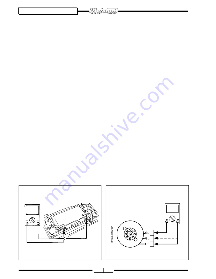
• Collegare il tester (DC 20V)
tester (DC 20V)
tester (DC 20V)
tester (DC 20V)
tester (DC 20V) alla batteria (F. 14):
- Terminale (+) tester: polo (+) batteria
- Terminale (-) tester: polo (-) batteria
• Misurare prima la tensione a motore spento.
• Collegare un contagiri al cavo candela.
• Avviare il motore a circa 5000 giri/min.
• La tensione di carica è data dalla tensione ricavata a
motore acceso, meno la tensione ricavata a motore spen-
to.
• La tolleranza della tensione di carica, può variare da
0,2 volt
0,2 volt
0,2 volt
0,2 volt
0,2 volt
a 2,5 volt
2,5 volt
2,5 volt
2,5 volt
2,5 volt (es.: tensione a motore spento = 12,7
12,7
12,7
12,7
12,7
volt
volt
volt
volt
volt – tensione a motore acceso = 13 volt
13 volt
13 volt
13 volt
13 volt
→
13 volt
13 volt
13 volt
13 volt
13 volt
-
12,7 volt
12,7 volt
12,7 volt
12,7 volt
12,7 volt = 0,3 volt
0,3 volt
0,3 volt
0,3 volt
0,3 volt)
.
-
Fuori specifica: proseguire la ricerca.
B)
B)
B)
B)
B) Controllo resistenza bobina di ricarica
Controllo resistenza bobina di ricarica
Controllo resistenza bobina di ricarica
Controllo resistenza bobina di ricarica
Controllo resistenza bobina di ricarica
• Rimuovere il connettore a tre vie (cavi gialli
gialli
gialli
gialli
gialli) del volano
magnete, e collegare il tester (
tester (
tester (
tester (
tester (
Ω
Ω
Ω
Ω
Ω
x 1)
x 1)
x 1)
x 1)
x 1) (F.
15):
- Terminale (+) tester: cavo giallo.
giallo.
giallo.
giallo.
giallo.
- Terminale (-) tester: cavo giallo
giallo
giallo
giallo
giallo, intercambiandoli.
intercambiandoli.
intercambiandoli.
intercambiandoli.
intercambiandoli.
- Resistenza bobina statore: da 0,6
da 0,6
da 0,6
da 0,6
da 0,6
Ω
Ω
Ω
Ω
Ω
a 1,6
a 1,6
a 1,6
a 1,6
a 1,6
Ω
Ω
Ω
Ω
Ω
.
.
.
.
.
-
Fuori specifica: sostituire statore.
-
Come da specifica: sostituire il regolatore.
A)
A)
A)
A)
A) Prüfung der Ladungsspannung (eine geladene
Prüfung der Ladungsspannung (eine geladene
Prüfung der Ladungsspannung (eine geladene
Prüfung der Ladungsspannung (eine geladene
Prüfung der Ladungsspannung (eine geladene
Batterie verwenden)
Batterie verwenden)
Batterie verwenden)
Batterie verwenden)
Batterie verwenden)
• Das Vielfachmessgerät (DC 20V)
Vielfachmessgerät (DC 20V)
Vielfachmessgerät (DC 20V)
Vielfachmessgerät (DC 20V)
Vielfachmessgerät (DC 20V) an die Batterie
anschließen (Abb. 14):
- Endverschluss Vielfachmessgerät (+): Batteriepol (+)
- Endverschluss Vielfachmessgerät (-): Batteriepol (-)
• Zuerst die Spannung beim abgeschalteten Motor
messen.
• Einen Drehzahlmesser an das Zündkerzenkabel
anschließen.
• Den Motor mit ca. 5000 Upm in Betrieb setzen.
• Die Ladungsspannung ist die Differenz zwischen der
Spannung, die beim eingeschalteten Motor erreicht
wird und der Spannung, die beim ausgeschalteten
Motor erreicht wird.
• Die Toleranz der Ladungsspannung kann von 0.2 Volts
0.2 Volts
0.2 Volts
0.2 Volts
0.2 Volts
bis 2.5 Volts
2.5 Volts
2.5 Volts
2.5 Volts
2.5 Volts ändern (z.B. Spannung beim
ausgeschalteten Motor = 12.7 Volts
12.7 Volts
12.7 Volts
12.7 Volts
12.7 Volts – Spannung beim
eingeschalteten Motor = 13 Volts
13 Volts
13 Volts
13 Volts
13 Volts
→
13 Volts – 12.7
13 Volts – 12.7
13 Volts – 12.7
13 Volts – 12.7
13 Volts – 12.7
Volts = 0.3 Volts
Volts = 0.3 Volts
Volts = 0.3 Volts
Volts = 0.3 Volts
Volts = 0.3 Volts)
- Außerhalb Spezifikation: weitersuchen.
B)
B)
B)
B)
B) Prüfung des Ladungsspulenwiderstands
Prüfung des Ladungsspulenwiderstands
Prüfung des Ladungsspulenwiderstands
Prüfung des Ladungsspulenwiderstands
Prüfung des Ladungsspulenwiderstands
• Den Drei-Weg-Verbinder (gelbe
gelbe
gelbe
gelbe
gelbe Kabel) von dem
Schwungmagnetzünder entfernen und das
Vielfachmessgerät (
Vielfachmessgerät (
Vielfachmessgerät (
Vielfachmessgerät (
Vielfachmessgerät (
Ω
Ω
Ω
Ω
Ω
x 1)
x 1)
x 1)
x 1)
x 1) (Abb. 15) anschließen:
- Endverschluss Vielfachmessgerät (+): gelbes
gelbes
gelbes
gelbes
gelbes Kabel.
- Endverschluss Vielfachmessgerät (-): gelbes
gelbes
gelbes
gelbes
gelbes Kabel
und austauschen.
austauschen.
austauschen.
austauschen.
austauschen.
- Statorspulenwiderstand: von 0.6
von 0.6
von 0.6
von 0.6
von 0.6
Ω
Ω
Ω
Ω
Ω
bis 1,6
bis 1,6
bis 1,6
bis 1,6
bis 1,6
Ω.
Ω.
Ω.
Ω.
Ω.
- Außerhalb Spezifikation: den Stator ersetzen.
- Innerhalb der Spezifikation: den Regler ersetzen.
F. 14
F. 15
F18 - 125
F18 - 125
F18 - 125
F18 - 125
F18 - 125cc / 150cc
cc / 150cc
cc / 150cc
cc / 150cc
cc / 150cc
Summary of Contents for F18 WARRIOR
Page 1: ...1 05 01 F18 WARRIOR F18 WARRIOR F18 WARRIOR F18 WARRIOR F18 WARRIOR ...
Page 145: ......
Page 146: ......
Page 147: ......
Page 148: ......
Page 149: ......
Page 150: ......


