36
08.06
PAGE
ISSUE
B
MADISON 125 cc
Signalling System
CHAPTER
ENGLISH
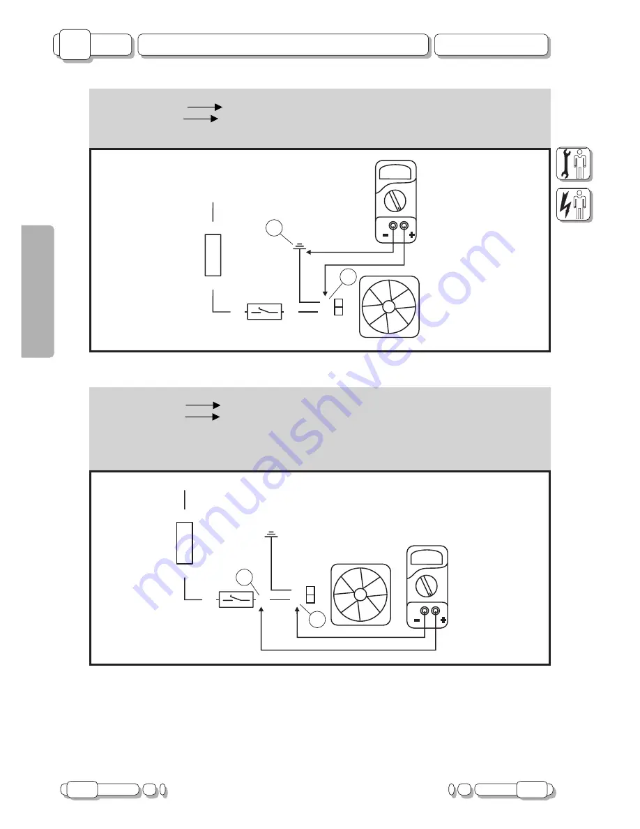
7.5 Check continuity of yellow
cable
- Connect
Tester (
:
:
:
:
:
)
to yellow cable leading from thermal switch to radiator fan connector, as follows:
- Terminal (+) of tester
Yellow
cable
(1).
- Terminal (+) of tester
Yellow
cable
(2).
- No continuity: the relative
yellow
cable is interrupted.
- Repair, see “Wiring Diagram”.
- Continuity:
yellow
cable leading from fuse holder to thermal switch is interrupted.
- Repair; see “Wiring Diagram”.
F. 52
N
R
N
GL
GL
GL
GL
FUS
7,5A
FUS
7,5A
AZ/GR
100°-95°
+12 V WITH KEY ON
7.4 Check ground continuity of black cable
- Connect
Tester (
:
:
:
:
:
)
as follows:
- Terminal (+) of tester
Black
cable
(1).
- Terminal (-) of tester
Chassis grounding (2).
- No continuity: black
cable
interrupted.
- Repair by providing a jumper between the
black
cable and a grounded point of the chassis.
F. 51
N
R
N
GL
GL
GL
GL
FUS
7,5A
FUS
7,5A
AZ/GR
100°-95°
1
2
+12 V WITH KEY ON
2
1


