46
02/08
F. 93
F. 94
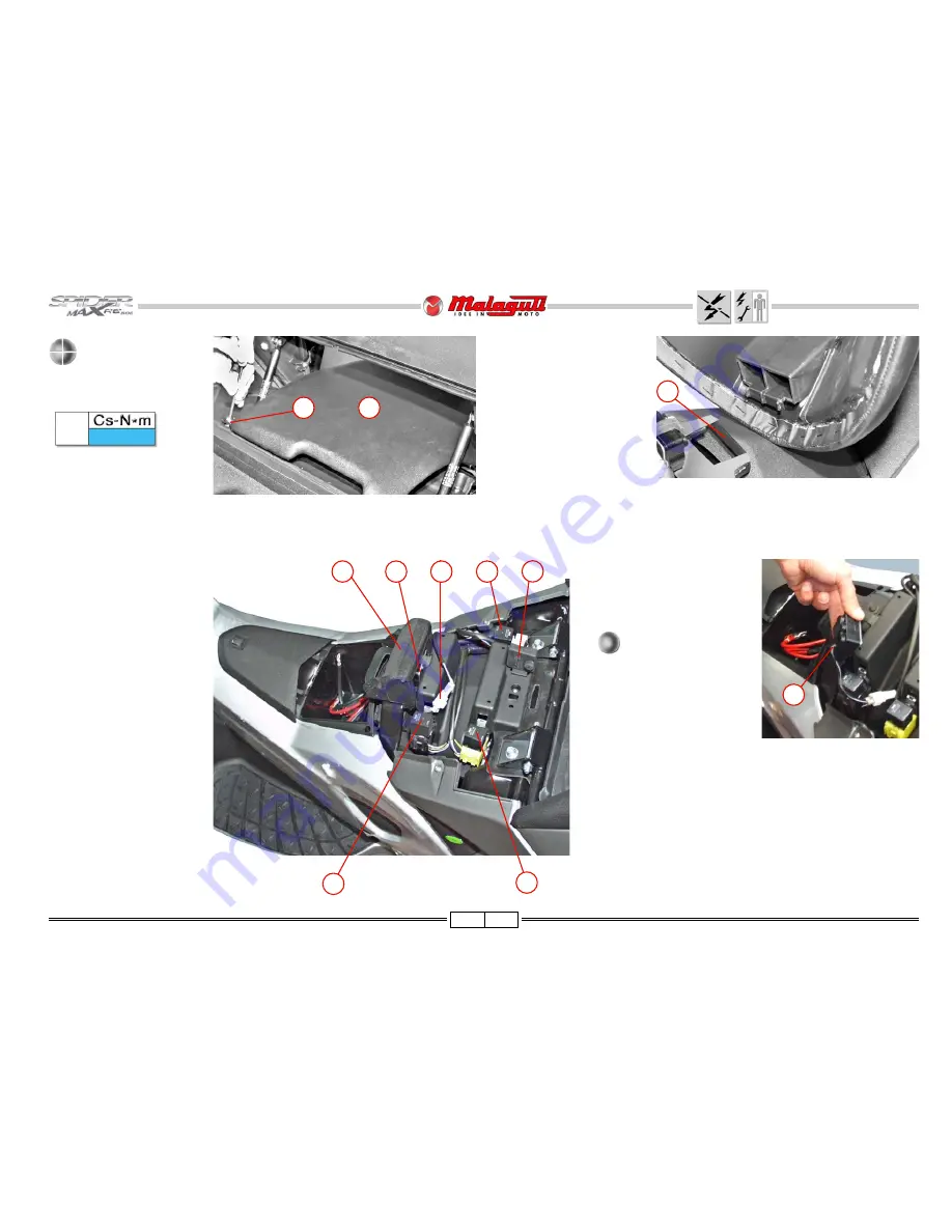
DRIVER
SEAT
• Release the screws (V2) on
the rear part.
• Remove the driver seat (A),
releasing it form the locking
tab (B).
V
2
5 ± 20%
V
2
A
ACCESSES
• Removing the driver seat,
allows reaching the following
electronic components:
A) Relay (black) - Starter
B) Relay (yellow) - Electric
fan
C) Relay (red) - Injection
system
D) Tilt sensor connector
E) Tilt sensor
F) Flasher
B
NOTE - In order to access the
tilt sensor (E) it is necessary
to remove the rubber protec-
tion (G).
When reassembling the
sensor, make sure that
the cable (H) is facing
downwards.
F. 96
G
A
B
F. 95
E
F
C
D
H
Summary of Contents for SPIDER MAX RS 500
Page 1: ......
Page 78: ...77 02 08 CABLE POSITIONING PIPE SYSTEM AND ANCHORING TIES F 198 F 199 ...
Page 79: ...78 02 08 F 200 ...
Page 80: ...79 02 08 F 201 ...
Page 81: ...80 02 08 F 202 ...


