background image

Federal Communications Commission
(FCC) Notice (US only)

The FCC mark on this product signifies conformance to FCC regulations
relating to Radio Frequency Devices. These have been satisfied by testing the
product against, and being found to be compliant with:

FCC CFR 47 Part 15:July 2001.Class A digital device.

The device complies with part 15 of the FCC Rules. Operation is subject to the
following two conditions:

1) This device may not cause harmful interference, and

2) this device must accept any interference received, including interference
that may cause undesired operation.

'

N o t e

.

This equipment has been tested and found to comply with the limits for
a Class A digital device, pursuant to part 15 of the FCC rules. These
limits are designed to provide reasonable protection against harmful
interference when the equipment is operated in a commercial
environment. This equipment generates, uses, and can radiate radio
frequency energy and, if not installed and used in accordance with the
instruction manual, may cause harmful interference to radio
communications. Operation of this equipment in a residential area is
likely to cause harmful interference in which case the user will be
required to correct the interference at his own expense.

'

N o t e

.

Changes or modifications not expressly approved by Malvern
Instruments Limited could void the user’s authority to operate the
equipment.

A P P E N D I X F

Z e t a s i z e r

N a n o

S e r i e s

P a g e F . 2

M

A

N

0

3

1

7

Summary of Contents for Zetasizer Nano Series

Page 1: ...Zetasizer Nano Series User Manual Zetasizer Nano Series User Manual M A N 0 3 1 7 I s s u e 1 0 J u n e 2 0 0 3...

Page 2: ...hanges errors or omissions after the date of publication No reproduction or transmission of any part of this publication is allowed without the express written permission of Malvern Instruments Ltd He...

Page 3: ...APTER 3 How does the Zetasizer Nano work Introduction 3 1 How is a Zetasizer measurement performed 3 1 What does the Zetasizer consist of Identifying the Hardware 3 4 Navigating the Software 3 13 CHAP...

Page 4: ...lacing the system fuse 7 4 Part 2 Supervisors guide CHAPTER 8 Security Introduction 8 1 Initial start up set up the administrator 8 2 Enabling security 8 3 User groups 8 3 Users 8 5 CHAPTER 9 Using SO...

Page 5: ...eport 12 4 A finished report 12 11 Viewing the new report 12 12 CHAPTER 13 Size theory Introduction 13 1 What is Dynamic Light Scattering 13 1 Operation of the Zetasizer Nano Size measurements 13 6 CH...

Page 6: ...pecification C 4 Laser Safety C 4 APPENDIX D Unpacking instructions APPENDIX E Installation Introduction E 1 Installing the Zetasizer Nano E 1 Changing the computer E 2 Installing the Titrator E 2 APP...

Page 7: ...Part 1 Operators guide Part 1 Operators guide...

Page 8: ......

Page 9: ...Introduction to this manual Introduction to this manual C H A P T E R 1...

Page 10: ......

Page 11: ...Nano S90 Green badge ZEN1590 Size measurement particle sizer 90 optics Nano ZS90 Red badge ZEN3690 Size and Zeta potential particle sizer 90 optics Nano ZS90 Green badge ZEN3590 Size and Zeta potentia...

Page 12: ...Zetasizer Nano and what do they do instructions on using the instrument and the software basic measurement and maintenance procedures Part 2 Supervisors guide The Supervisors guide concentrates on the...

Page 13: ...uthorised to perform all service procedures that may require the removal of the covers Warning Supervisor The supervisor is the person responsible for the management and safety of the instrument and i...

Page 14: ...u commands from the Zetasizer software are referred to in the form main menu menu item As an example the command Configure New SOP refers to selecting the New SOP item in the Configure menu Menu comma...

Page 15: ...model and serial number labels identifies any options fitted The Zetasizer software version select Help About within the software Contact the United Kingdom help desk if the local Malvern representati...

Page 16: ...C H A P T E R 1 Z e t a s i z e r N a n o S e r i e s Page 1 6 M A N 0 3 1 7...

Page 17: ...What is the Zetasizer Nano What is the Zetasizer Nano C H A P T E R 2...

Page 18: ......

Page 19: ...measurements The Zetasizer range features pre aligned optics and programmable measurement position plus the precise temperature control necessary for reproducible repeatable and accurate measurements...

Page 20: ...table for blue samples The 532nm laser is least suitable for red samples 90 optics The instruments above with the suffix 90 indicate the optics have a 90 scattering angle These models have been includ...

Page 21: ...mines the size by first measuring the Brownian motion of the particles in a sample using Dynamic Light Scattering DLS and then interpreting a size from this using established theories see chapter 13 B...

Page 22: ...f Particle size is important in developing stable formulations of pigments Pigment colour and hue are highly related to particle size this has applications in determining a pigments properties What is...

Page 23: ...can determine how many grams there are in 1 mole of a substance The mole being the chemistry standard term for 1 molecular weight e g one mole of water is 18 015g In an application knowing the molecu...

Page 24: ...Electrophoresis This method measures how fast a particle moves in a liquid when an electrical field is applied i e its velocity Once we know the velocity of the particle and the electrical field appl...

Page 25: ...ly charged salts Measurement of zeta potential in combination with these parameters is fundamental in the development and maintenance of optimized water treatment protocols Emulsions Zeta potential is...

Page 26: ...C H A P T E R 2 Z e t a s i z e r N a n o S e r i e s Page 2 8 M A N 0 3 1 7...

Page 27: ...How does the Zetasizer Nano work How does the Zetasizer Nano work C H A P T E R 3...

Page 28: ......

Page 29: ...how the software performs the task This is followed by two sections identifying the major hardware components and the software used The complete measurement process for size zeta potential and molecul...

Page 30: ...from the menu bar and select an SOP to use With an SOP chosen the Measurement display will appear below The measurement will begin by pressing the Start button Manual Measurement A manual measurement...

Page 31: ...et reports or a user defined report The measurement results will be automatically saved to a measurement file N o t e The measurement file must be selected before the measurement is started as the mea...

Page 32: ...d It is preferable the computer is dedicated to just running the Zetasizer software The software controls the Zetasizer and any accessories used and analyses the data from the instrument to give eithe...

Page 33: ...socket for the instrument Fuse holder Fuse for the instrument Details on changing the fuses can be found in chapter 7 Maintenance Power switch The on off power switch for the instrument On switch on...

Page 34: ...rument options fitted into the Zetasizer For an explanation refer to the identification table in chapter 2 J Accessory output A 12v output supply is provided on the rear panel to connect to any Malver...

Page 35: ...around the Cell access button and shows the operational state of the instrument Indicator colour and state Function Amber Flashing Shows the start up initialisation routine is running Amber Shows tha...

Page 36: ...area temperature above 50 C the instrument will beep twice every few seconds to warn of high temperatures N o t e When the Zetasizer is initially switched on the cell area will be driven to a default...

Page 37: ...oltage interlock This interlock immediately turns off any voltage to the cell electrodes To close the lid push it down until it locks No measurements can be performed unless the lid is fully closed El...

Page 38: ...ator accessory The channel includes a pinch valve to hold the tubes in place and stop sample movement during the measurement To fit the tubes slide them into the channel until clamped by the pinch val...

Page 39: ...there is a drain incorporated into the base of the cell holder Any spillage will exit onto the bench area underneath the Zetasizer I Drain channel Likewise in case of spillage on the cover a drainage...

Page 40: ...e The Zetasizer Nano model serial number software and firmware version can be found by left clicking the Nano icon in the right corner of the status bar 1 Cells and Cuvettes A range of cells and cuve...

Page 41: ...e The main Zetasizer application which is described below A secondary module known as Report Designer which enables custom re ports to be created to display the results The features of Report Designer...

Page 42: ...to Open or create a New measurement file The measurement file is where all the measurement records results will be stored Select Save as to store a measurement file under a different file name Once a...

Page 43: ...e bottom of the Records view listing To view the settings for any particular measurement record select the record and then Extract SOP The SOP dialogues will appear showing the original measurement se...

Page 44: ...kspace with the Configure Workspace dialogues The reports available will change to match the workspace chosen Select Status bar to toggle the status bar from being displayed or not Configure Menu Use...

Page 45: ...rameters shown in the Records view tab are those selected when creating the measurement file workspace with the Workspace dialogues The dialogues enable workspaces to be deleted and Added or previousl...

Page 46: ...vern authorised service engineers to perform maintenance tasks The engineering screens are password protected Security Menu To prevent unauthorised changes the Malvern software can be configured to li...

Page 47: ...use the Zetasizer software a different tip will appear each time this is selected An option is given for turning off the Tip of the day dialogue that appears when the software starts About gives detai...

Page 48: ...s it may be unnecessary to see parameters associated with size measurements in the measurement file window A measurement file workspace called zeta potential is available that displays only parameters...

Page 49: ...hen a measurement is being performed a measurement display below will appear showing the progress of the measurement The screen display shown depends on the type of measurement being performed and the...

Page 50: ...is not detailed in this manual Malvern defined features Within the software various parameters settings or reports will have either a small Malvern logo or an M alongside This identifies it as Malvern...

Page 51: ...Making measurements A tutorial Making measurements A tutorial C H A P T E R 4...

Page 52: ......

Page 53: ...y a one off measurement where all the measurement parameters are set up immediately prior to the measurement This is ideal if measuring many different types of sample or experimenting with the measure...

Page 54: ...wn When requested insert the cell into the instrument and wait for the tem perature to stabilise Click Start The measurement will be made and the results displayed and saved to the open measurement fi...

Page 55: ...re it is inserted into the instrument is paramount Please refer to Chapter 6 for sample preparation guidelines for the different measurement types Choosing the correct Cell Malvern offers a range of c...

Page 56: ...ssible spillage Caution Size measurements Size Zeta Folded Capillary cell DTS1060 Disposable polystyrene DTS0012 Typical solvent Water Water alcohol Water Water ethanol Optical quality Good to very go...

Page 57: ...vents Unsuitable for use at high temperatures above 50 C Requires cleaning after measurement Glass square aperture PCS1115 Low volume quartz DTS2145 Typical solvent Water most organic and inorganic so...

Page 58: ...bubbles Molecular weight measurements Glass round aperture PCS8501 Glass square aperture PCS1115 Typical solvent Water most organic and inorganic solvents Water most organic and inorganic solvents Opt...

Page 59: ...s to provide leak free connection to the optional MPT2 Autotitrator Size measurements can also be performed without having to remove and reposition the cell Sample details can be written on the textur...

Page 60: ...for aqueous samples and the green capped cell used for non aqueous Filling the Cell When filling the cell there are several actions to consider some that applies to all cells and other actions that ar...

Page 61: ...ta measurements are the folded capillary cell and the dip cell the dip cell will use square cuvettes to hold the sample Though filling either cell is a simple task there are a number of precautions to...

Page 62: ...f the sample ports Slowly inject the sample through the cell checking that all air bubbles are removed If a bubbles forms under the sam ple port pull the syringe plunger back to draw the bubble into t...

Page 63: ...ave opaque surfaces as well as polished optical surfaces A polished optical surface must be facing the front of the instrument towards the button Most cells have a small triangle at the top to indicat...

Page 64: ...rent insertion routines N o t e The electrode contacts on each cell as well as applying the measurement voltage provide identification to the software of which zeta potential cell is fitted Inserting...

Page 65: ...te Place the dip cell fully into the cuvette Some cells have opaque surfaces as well as polished optical surfaces Ensure the small triangle at the top of the cell faces the front of the instrument Che...

Page 66: ...rement file may be used for all the measurement records not recommended Separate files are used for each type of sample i e one for titanium dioxide and one for carbon black A separate measurement fil...

Page 67: ...for the sample read chapter 9 for details on how to create one Pre measurement instructions may appear to advise of any actions that need to be performed before the measurement can proceed This may be...

Page 68: ...ement options are pre specified it will be necessary to set them immediately All the dialogues are available at once in a tabbed format Follow the measurement procedures described above Instead of sta...

Page 69: ...shows the display for a size measurement The features of the measurement display are Button bar The button bar provides the control for the measurement operation Settings Opens the measurement settin...

Page 70: ...measurement position and attenuator settings Progress meter The progress meter shows how far the measurement has progressed plus the number of measurements performed and the measurement runs complete...

Page 71: ...on A steadily increasing count rate will indicate an aggregating sample while a decreasing count rate will indicate a sedimenting sample Log sheet Displays the progress of the measurement Correlation...

Page 72: ...concentration measurements The result shown will be an evolving value from the data collected so far Debye Displays the current result as a Debye plot The Debye plot displayed will show an evolving pl...

Page 73: ...s compensation and attenuator settings for the cell sample and measurement type will be determined Monitoring the status bar or clicking on the Log sheet tab will give more detail about what is happen...

Page 74: ...to prompt insertion of the first sample concentration i e the pure solvent Insert the first sample concentration and press start The software displays another dialogue where the sample concentration c...

Page 75: ...layed and saved to the current open file This report pages can be viewed when the measurement display has been closed Editing the result It is possible to re analyse a measurement record using differe...

Page 76: ...can be displayed in the Records view tab by selecting the Measurement Audit information Reason in the Workspace settings dialogue Select Configure Workspaces workspace choice and then the Record view...

Page 77: ...Records and Reports Viewing the results Records and Reports Viewing the results C H A P T E R 5...

Page 78: ......

Page 79: ...elected measurement record N o t e The Records view parameters and Report tabs that are displayed are dependent upon the Workspace settings selected refer to chapter 10 Records view Once the measureme...

Page 80: ...f the measurement and the date printed plus the Malvern contact phone number Each measurement type has a standard report associated to it The same result information is present in both the computer an...

Page 81: ...e cell type selected Attenuation index The laser power is automatically attenuated so that the count rate from the sample especially high scattering samples is within acceptable limits An attenuation...

Page 82: ...cally moved to allow a large range of sample concentrations to be measured The default measurement position is 4 65mm from the cell wall when a 12mm square cuvette is used Numbers lower than this indi...

Page 83: ...nly be used to compare results with samples measured in the same dispersant by the same technique i e by Dynamic Light Scattering DLS The cumulants analysis only gives two values a mean value for the...

Page 84: ...raphical form The format of the graph can be altered by moving the cursor over the graph and right clicking the mouse The Graph control properties dialogue will appear This dialogue allows the followi...

Page 85: ...into a graph report Simply hold down the left mouse button and move the mouse to draw a Marquee from top left to bottom right around the area to be enlarged To zoom back out simply click the left mou...

Page 86: ...e description for details System details The System section gives details on settings configured during the measurement process Please see the size description for details about Temperature Cell type...

Page 87: ...e interaction strength between the molecule and the solvent Fit error This is an indication of the quality of the measurement The lower the fit error the better the measurement Graph The results are a...

Page 88: ...ettings specific for zeta measurements are Mean Count rate Average count rate for the measurement F ka value Displays the Henry function or approximation used during the measurement A value of 1 5 mea...

Page 89: ...the size description above for details on altering the graph Other Zeta potential reports Other Malvern views available for zeta potential measurements are Electrophoretic mobility M This report is ef...

Page 90: ...C H A P T E R 5 Z e t a s i z e r N a n o S e r i e s Page 5 12 M A N 0 3 1 7...

Page 91: ...Sample Preparation Sample Preparation C H A P T E R 6...

Page 92: ......

Page 93: ...to make a measurement This is unlikely to occur with the Zetasizer except in extreme circumstances If the sample is too concentrated then light scattered by one particle will it self be scattered by...

Page 94: ...ncentrations below 0 1 by volume Be aware that particle interactions may occur at sample concentrations larger than 1 by volume particle interactions will influence the results Considerations for smal...

Page 95: ...s so small fewer than 10 that severe fluctuations of the momentary number of particles in the scattering volume will occur These fluctuations are not the type assumed by the calculation method used or...

Page 96: ...contaminating the sample The size of the filter will be determined by the estimated size of the sample If the sample is 10nm then 50nm dust will be an important contaminant in the dispersant Aqueous d...

Page 97: ...scratches Preparation of samples and storage of apparatus in a laminar flow cabinet to ensure minimisation of dust contamination is strongly recommended Failure to carry out these routine procedures...

Page 98: ...s are not as strict as those used for size and molecular weight measurements An auto attenuator fitted inside the instrument ensures that the sample count rate is suitable for the requirements of the...

Page 99: ...Zeta potential is not a size dependent parameter using the approximation of the Smoluchowski theory Another method is to imitate the original medium as closely as possible This should be done with reg...

Page 100: ...C H A P T E R 6 Z e t a s i z e r N a n o S e r i e s Page 6 8 M A N 0 3 1 7...

Page 101: ...Maintenance Maintenance C H A P T E R 7...

Page 102: ......

Page 103: ...d all electrical cables are disconnected Never use excessive liquid to clean the instrument and always avoid elec trical components connectors etc Always ensure that the instrument is completely dry b...

Page 104: ...nutes before use For the cleaning fluid use the dispersant used for the previous sample If the dispersant contains additives such as surfactants fol low this by ultrasonicating for two minutes in the...

Page 105: ...easured therefore specific instructions can not be given here However the following advice should be followed Rinse the cuvette with the same dispersant that was used for the measure ment i e if the s...

Page 106: ...uses disconnect the instrument from the mains power supply Pull the fuse holders out and replace any faulty fuses with ones of the following specification Rating Size T 2A L 250v T Time delay 5mm x 20...

Page 107: ...Part 2 Supervisors guide Part 2 Supervisors guide...

Page 108: ......

Page 109: ...Security Security C H A P T E R 8...

Page 110: ......

Page 111: ...ach operator a password Each operator s identification and password are entered to enable access to the software The first time the software is run the security system will be disabled and an administ...

Page 112: ...oup is originally set to only allow configuration of the security system and to deny access to all other features of the system On first start up of the software the security system defaults to a memb...

Page 113: ...onfiguration dialogue select Options Security settings and select the Enable security check box With security enabled each user must login when the software starts Once logged in only their relevant p...

Page 114: ...ation and SOP creation Administrators Users authorised to configure the security system The Members section of the dialogue shows a list of all the users currently assigned to the group To add a user...

Page 115: ...configuration dialogue Select User New User to display the User properties dialogue alternatively double click on an empty row When editing double click on an existing user to display the dialogue Eac...

Page 116: ...ons to allocate the groups or groups appropriate Password options User must change password at next logon The change password dialogue will be shown when the user next logs in allowing the user to cha...

Page 117: ...is advisable for users to regularly change their passwords to prevent unauthorised access The only possible exception is the security administrator s account where forgetting the password to this acco...

Page 118: ...C H A P T E R 8 Z e t a s i z e r N a n o S e r i e s Page 8 8 M A N 0 3 1 7...

Page 119: ...Using SOPs Using SOPs C H A P T E R 9...

Page 120: ......

Page 121: ...e This chapter focuses on how to create a new SOP and details all the measurement settings that are available Almost all the options for creating an SOP are the same as those available for making a ma...

Page 122: ...ments made using this SOP are given the sample name entered in the SOP by default but you can give an option to change this when you make the measurement Information can be entered in the General note...

Page 123: ...on dialogue for all SOPs with unique features dependent upon the measurement type Reports This dialogue enables reports to be automatically printed after each measurement and or after a run of measure...

Page 124: ...dialogues Measurement type The initial dialogue is always the Measurement type selection From the drop down list select the type of measurement the SOP will perform either Size Protein melting point...

Page 125: ...at use the SOP unless the Show this page when the SOP is started check box is selected and the text modified Show this page when the SOP is started With this check box selected the Labels dialogue wil...

Page 126: ...ctly and consistently e g The SOP creator may give comments that inform that this SOP should only be used for certain batches of sample Detail can be provided to describe how to prepare the sample Dis...

Page 127: ...Malvern for compatibility The software will automatically determine the measurement conditions for the cell type selected i e cell position for size cells and applied voltage for the zeta potential ce...

Page 128: ...pleted and the other to print out a report after all measurements have been completed For each select the Print reports check box and then the reports required Any reports created using Report Designe...

Page 129: ...y a template using the Templates button this will display the export dialogues described in chapter 11 Refer to this chapter for full details on creating the export templates The parameters will be ex...

Page 130: ...properties can be defined Dispersant properties To define a new dispersant press the Add button The Dispersant properties dialogue will appear allowing new dispersants to be defined The dispersant na...

Page 131: ...ist The dispersant properties dialogue will appear allowing the parameters to be changed A dispersant can be deleted by selecting the dispersant from the list and pressing the Delete button Note that...

Page 132: ...tion that the sample viscosity is the same as the dispersant viscosity is usually valid If this is not the case or at higher sample concentrations over 0 1 then the sample viscosity should be measured...

Page 133: ...d K parameters both available in many reference books the molecular weight can be determined Once entered both a molecular weight calculation and size measurement will be available for display Measure...

Page 134: ...ed temperature is from current temperature the longer it will take for the sample to reach a stable temperature When should the cuvette be placed into the instrument A choice is given to either insert...

Page 135: ...le size over time or to prove repeatability Set the Number of measurements to that required Add a delay between measurements in the Delay between measurements text box if required The Append measureme...

Page 136: ...lation Size ranges and measurement thresholds can be applied to the analysis to filter spurious peaks out prior to the analysis being performed Please see the Advice button for more information Genera...

Page 137: ...to volume and number will then ignore the data outside the set limits Similarly lower and upper thresholds can be applied to eliminate undesired populations that are below a defined percentage of the...

Page 138: ...l refractive index increment dn dc of the solvent This is the change in refractive index as a function of the change in concentration For many sample solvent combinations this may be available in lite...

Page 139: ...bration By selecting either the Material Solvent or Standard tab and selecting the button these properties can be defined Solvent properties tab Selecting this tab enables new solvents to be added and...

Page 140: ...perature Refractive index and Rayleigh ratio This will nearly always be Toluene The standard properties can be added modified and deleted in the same way as the solvents detailed previously Measuremen...

Page 141: ...hape correction model used for the measurement With knowledge of the sample structure it is possible to improve the result of the measurement by adding the value that most closely corresponds to the p...

Page 142: ...howski 1 5 For non aqueous measurements the Huckel approximation should be used 1 0 Please refer to chapter 15 for more information on the F ka model Material and Dispersant properties The Zetasizer s...

Page 143: ...ription in the size SOP section for details Material properties tab Selecting this tab allows new material to be added and selected Define a new material by selecting the Add button and entering the m...

Page 144: ...nts of the same sample Temperature Please refer to the Temperature description in the size SOP section Measurement Duration The measurement duration setting affects the accuracy and repeatability of t...

Page 145: ...are accumulated and then averaged to give a final zeta potential result Therefore the more runs performed the better the repeatability Naturally the more runs selected the longer the duration of the c...

Page 146: ...reater than 5milliSiemans Advanced The Advanced button dialogue enables both the measured Zeta potential range and the measurement thresholds to be set If it known that all particles within the sample...

Page 147: ...s being the inclusion of a trend and altered measurement dialogues Trend Enables the selection of the temperature trend parameters i e start and end temperatures and intervals between measurement step...

Page 148: ...cuvette Melting point measurements only Stop when melting point found If this check box is selected the measurement will stop once the melting point has been determined Return to Start temperature If...

Page 149: ...name Modifying an SOP To modify an SOP select Configure Existing SOP The same dialogues as explained above will be displayed allowing any settings to be changed In this case they will be displayed in...

Page 150: ...o instrument so that measurements are done consistently Simply copy the SOP file to all computers running a Zetasizer Nano system If the SOP has a non standard dispersant defined then this will not ex...

Page 151: ...Measurement file window Workspace management Measurement file window Workspace management C H A P T E R 1 0...

Page 152: ......

Page 153: ...create their own custom reports to satisfy their individual needs Details on creating custom reports using Report Designer are given in chapter 12 Generally a computer screen displays information in...

Page 154: ...ords view tab and then select the appropriate report tab The report tabs will be greyed out if no mea surement is selected What measurement information is presented in the Report and Record tabs is co...

Page 155: ...ze Molecular weight Zeta potential and Summary workspaces are available with Record view parameters and Report pages already configured To display an existing workspace window select View Workspaces w...

Page 156: ...leted the new workspace can be selected using the View menu or Workspace toolbar The workspace toolbar can be turned on and off by selecting View Workspace Workspace Toolbar Record view With the Summa...

Page 157: ...ting a parameter and pressing the Move up or Move Down buttons Press OK to exit and return to the Records view Parameters with arguments Certain parameters allow specific values or arguments to be add...

Page 158: ...lecular weight M These and other reports can be added or removed using the workspace dialogues Selecting a report to view Select Configure Workspaces workspace choice and then the Report Pages tab Sel...

Page 159: ...antly remove any selected records from the measurement file They will not be deleted from the software but be stored in a DEL file in the DTS Measurement data directory This file has the same name as...

Page 160: ...can be chosen using standard Windows procedure Either click a single record or hold down Shift or Ctrl and choose either sequential or non sequential records C H A P T E R 1 0 Z e t a s i z e r N a n...

Page 161: ...Exporting results Exporting results C H A P T E R 1 1...

Page 162: ......

Page 163: ...ed to specify which record pa rameters are exported The Configure Data export templates dialogue allows you to create and modify your own templates A complete measurement file or selection of records...

Page 164: ...If necessary a new template can be created or an existing one edited This will be dis cussed later in this chapter Creating an export template Settings tab This tab determines how the data is exporte...

Page 165: ...xport template New export templates can be created or existing ones modified by selecting Configure Data exports templates Two export templates are supplied as standard Cumulative Undersize and Freque...

Page 166: ...displayed by selecting a parameter and using the Move up or Move Down buttons Press OK to exit and return to the Data exports templates dialogue Press OK again to save the template Parameters with ar...

Page 167: ...entile d 99 to reflect the particular percentile size viewed The Settings tab works the in the same way as previously described N o t e The Export templates can also be selected and edited using the S...

Page 168: ...C H A P T E R 1 1 Z e t a s i z e r N a n o S e r i e s Page 11 6 M A N 0 3 1 7...

Page 169: ...Creating custom reports Creating custom reports C H A P T E R 1 2...

Page 170: ......

Page 171: ...o not have to be identical for example company logos can be added to the printed reports while not showing them on the display Report Designer enables the user to add and alter the following items to...

Page 172: ...y opening an existing one customising it to suit and then saving it under a different name For both ways formatting the layout of a report and customising the content is the same Laying out a report T...

Page 173: ...left Align right Align top Align bottom Make same width Make same height Make same size The Layout menu also contains extra functions to Space evenly and Centre the object When two or more objects are...

Page 174: ...menu The sections below show the properties each object can display Text Within the text properties dialogue the text can be edited and its font alignment colour and size altered Parameter The paramet...

Page 175: ...the report into relevant sections By using the properties dialogue the frame style can be chosen etched raised sunken etc and its colour changed Horizontal and vertical lines can be inserted into the...

Page 176: ...within the editor by selecting the icon The calculation will only display a value for records that have been created since the calculation was set up To obtain a result in a calculation on a record c...

Page 177: ...rom the size distribution displayed Statistics The statistics graph will show the mean standard deviation maximum and minimum of a group of selected measurement records The statistics shown on the tab...

Page 178: ...serted Display or Option will appear in the properties dialogue The Display tab allows a choice of graph type and how it is to be displayed i e as a histogram or curve The Options tab or selection box...

Page 179: ...ter and pressing the icon or double clicking the parameter will again display the Select a parameter dialogue The Against selection area is used for selecting the X axis parameter Selection is the sam...

Page 180: ...e size result of the measurement It can be displayed as Size Intensity Size Volume and Size Number using its properties box Statistics The statistics graph will show the mean standard deviation maximu...

Page 181: ...d press OK Refer to the Parameters properties dialogue for more details Any available parameter can be selected and inserted into the report The parameter value displayed is taken from the selected me...

Page 182: ...are by selecting Configure Workspaces and then selecting the workspace for the new report to be associated with In the Report Pages tab select the check box of the newly created report and press OK Wh...

Page 183: ...Size theory Size theory C H A P T E R 1 3...

Page 184: ......

Page 185: ...o known as PCS Photon Correlation Spectroscopy measures Brownian motion and relates this to the size of the particles It does this by illuminating the particles with a laser and analysing the intensit...

Page 186: ...that small particles move quickly and large particles move more slowly The relationship between the size of a particle and its speed due to Brownian motion is defined in the Stokes Einstein equation A...

Page 187: ...In this situation it is said that there is no correlation between the two signals With DLS we are dealing with very small time scales In a typical speckle pattern the length of time it takes for the...

Page 188: ...as the rate of decay is much faster for small particles than it is for large After the correlation function has been measured this information can then be used to calculate the size distribution The Z...

Page 189: ...mber of particles The second graph shown the result of the volume distribution The area of the peak for the 50nm particles is 1000 times larger the peak for the 5nm 1 1000 ratio This is because the vo...

Page 190: ...ct the scattering With the Zetasizer Nano series depending upon the particular model the detector position will be at either 173 or 90 The intensity of the scattered light must be within a specific ra...

Page 191: ...are will analyse the data and derive size information As mentioned earlier depending upon the Zetasizer Nano model the detection optics will either be arranged at positions of either 173 or 90 173 det...

Page 192: ...of high concentration scatter much more light In this situation measuring closer to the cell wall will reduce the effect of multiple scattering In this instance the flare from the cell wall will have...

Page 193: ...Molecular Weight theory Molecular Weight theory C H A P T E R 1 4...

Page 194: ......

Page 195: ...of measuring the time dependent fluctuations in the scattering intensity Static light scattering makes use of the time averaged intensity of scattered light instead The intensity of light scattered ov...

Page 196: ...mple solvent combinations this may be available in literature while for novel combinations the dn dc can be measured by use of a differential refractometer The standard approach for molecular weight m...

Page 197: ...ferent positions on the same particle as shown below This phenomenon is known as Mie scattering and it occurs when the particle is large enough to accommodate multiple photon scattering However when t...

Page 198: ...of various concentrations C of sample at one angle this is compared with the scattering produced from a standard i e Toluene The graphical representation of this is called a Debye plot and allows for...

Page 199: ...t of K CRq versus C should give a straight line whose intercept at zero concentration will be 1 M and whose gradient will be A2 C H A P T E R 1 4 Z e t a s i z e r N a n o S e r i e s Page 14 5 C conc...

Page 200: ...C H A P T E R 1 4 Z e t a s i z e r N a n o S e r i e s Page 14 6 M A N 0 3 1 7...

Page 201: ...Zeta Potential theory Zeta Potential theory C H A P T E R 1 5...

Page 202: ......

Page 203: ...the following sections Zeta potential and the Electrical double layer The development of a nett charge at the particle surface affects the distribution of ions in the surrounding interfacial region r...

Page 204: ...les with zeta potentials more positive than 30mV or more negative than 30mV are normally considered stable The most important factor that affects zeta potential is pH A zeta potential value on its own...

Page 205: ...effects There are four distinct effects depending on the way in which the motion is induced These are Electrophoresis The movement of a charged particle relative to the liquid it is suspended in unde...

Page 206: ...the particle by application of the Henry equation The Henry equation is z Zeta potential UE Electrophoretic mobility e Dielectric constant h Viscosity Ka Henrys function Two values are generally used...

Page 207: ...rength as their mobility The technique used to measure this velocity in Malvern s Zetasizer Nano series of instruments is Laser Doppler Velocimetry Laser Doppler Velocimetry Laser Doppler Velocimetry...

Page 208: ...ith possibly millions of particles observed The Electroosmosis effect The walls of the capillary cell carry a surface charge so the application of the electric field needed to observe electrophoresis...

Page 209: ...n samples of very low mobility to be analysed and their mobility distributions calculated The M3 PALS technique To perform measurements at any point within a cell and obtain the electrophoretic mobili...

Page 210: ...ents for each Zeta potential measurement one with the applied field being reversed slowly the SFR measurement and a second with a rapidly reversing applied field the FFR measurement stage Slow Field R...

Page 211: ...roosmosis The mean zeta potentials calculated from the FFR and SFR measurements are subtracted to determine the electroosmotic flow This value is used to normalise the slow field reversal distribution...

Page 212: ...nerated signal with that of a reference frequency the reference frequency being that of the optical modulator it is possible to see very small shifts or displacements in a particles movement that woul...

Page 213: ...e of the sample cell and the scattering at an angle of 17 is detected On insertion of the cell into the cell holder the cell terminals allow the system to recognise the type of zeta potential cell fit...

Page 214: ...re light such as large particles or samples of higher concentration the amount of scattered light must be decreased The attenuator will automatically reduce the amount of light that passes through to...

Page 215: ...Part 3 Appendices Part 3 Appendices...

Page 216: ......

Page 217: ...Health and Safety Health and Safety A P P E N D I X A...

Page 218: ......

Page 219: ...s should be treated accordingly Do not place cables in positions where they are likely to become wet A P P E N D I X A Z e t a s i z e r N a n o S e r i e s Page A 1 The instrument or the samples to b...

Page 220: ...rument Laser Safety Regulations The Zetasizer Nano series are Class 1 laser products and as such there is no exposure to laser radiation in the normal operation of the instruments Caution The diagram...

Page 221: ...fore using any substance check the Material Safety Data Sheets for safe handling information Use the instrument in a well ventilated room or preferably within a fume cupboard if the fumes from the sam...

Page 222: ...ages should occur then the system should be disconnected from the power supply before scrupulously cleaning up the spillage Moving the system If it is necessary to move the system the following guidel...

Page 223: ...Specification Specification A P P E N D I X B...

Page 224: ......

Page 225: ...20 l 3ml Measurement technique Size Nano S and ZS Nano S90 and ZS90 Zeta potential Molecular weight Dynamic light scattering NIBS Dynamic light scattering 90 degrees M3 PALS Static light scattering La...

Page 226: ...condensing Operating systems Windows XP Professional Service pack 1a or higher Windows 2000 Service pack 3 or higher Minimum computer specification Pentium PC 2GHz 128MByte RAM 80MByte free hard disk...

Page 227: ...Site requirements f r o m M A N 0 3 1 7 I s s u e 1 0 Site requirements A P P E N D I X C...

Page 228: ...hanges errors or omissions after the date of publication No reproduction or transmission of any part of this publication is allowed without the express written permission of Malvern Instruments Ltd He...

Page 229: ...ontal and vibration free It must also be capable of supporting the weight of the system The table be low lists the weights of the components of the system Zetasizer Nano 19 4kg MPT2 Autotitrator 5 3kg...

Page 230: ...imensions of all components of the system are given below Component Width Depth Height Zetasizer Nano 320mm 600mm 260mm MPT2 Autotitrator 170mm 390mm 260mm Computer and printer See manufacturers docum...

Page 231: ...es at low temperatures there is a risk of condensation occurring on the cell this occurs when the measurement temperature is less than the dew point of the ambient air surrounding the cell being measu...

Page 232: ...Service pack 3 or later Laser Safety The Zetasizer Nano series instruments are Class 1 laser products and as such require no special laser safety considerations during normal operation However during...

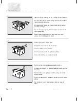
Page 233: ...e 1 0 D ballez l instrument Auspacken des Gerates Desempaquetado del aparato Desempacotamento do instrumento Unpacking instructions D ballez l instrument Auspacken des Gerates Desempaquetado del apara...

Page 234: ...ng straps D coupez les courroies d attache en plastique Die Kunststoffb nder durchschneiden Cortar las tiras de sujeci n de pl stico del embalaje Corte as tiras pl sticas que prendem o conjunto 3 Care...

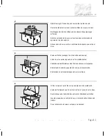
Page 235: ...autres paquets du carton et d ballez les S mtliche andere Pakete aus dem Karton nehmen und auspacken Retirar todos los dem s paquetes de la caja y desenvolverlos Retire todas as outras embalagens da c...

Page 236: ...mpre el aparato sobre sus patas Depositarlo de costado da ar a las cubiertas Coloque sempre o instrumento na vertical sobre os seus p s Se o colocar de lado ir danificar as tampas 9 Retain all packagi...

Page 237: ...Installation Installation A P P E N D I X E...

Page 238: ......

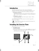
Page 239: ...company policy to periodically upgrade computers Detail is given on actions required Only install the system in a suitable enviroment as detailed in appendix C Enviromental conditions Do not obstruct...

Page 240: ...nt in the future the computer used with the instrument is changed the following actions will be required To install the software Insert the Dispersion Technology Software CD into the CD drive If Autor...

Page 241: ...Regulatory Statements Regulatory Statements A P P E N D I X F...

Page 242: ......

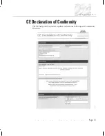
Page 243: ...CE Declaration of Conformity The CE badge on this product signifies conformance to European Commission Directives A P P E N D I X F Z e t a s i z e r N a n o S e r i e s Page F 1 ILL 6784...

Page 244: ...ly with the limits for a Class A digital device pursuant to part 15 of the FCC rules These limits are designed to provide reasonable protection against harmful interference when the equipment is opera...

Page 245: ...ommunications Note that Canadian Department of Communications DOC regulations provide that changes or modifications not expressly approved by Malvern Instruments Limited could void your authority to o...

Page 246: ...A P P E N D I X F Z e t a s i z e r N a n o S e r i e s Page F 4 M A N 0 3 1 7...

Page 247: ...Index Index...

Page 248: ......

Page 249: ...Cleaning 7 2 Dip cell 4 8 15 12 Filling 4 8 Flare 13 8 Flowcell 3 10 Identification 3 10 Inserting 4 11 Molecular weight 4 6 Size 4 4 Zeta potential 4 7 Cell SOP 9 2 9 7 Cell access button 3 8 Cell ar...

Page 250: ...5 8 14 2 Drainage 3 11 DTS E 2 Dust 4 19 Dynamic Light Scattering 2 3 13 1 E Earth connection A 2 E 2 Earthing A 2 Edit menu 3 15 Edit result 3 15 4 23 Electrical warnings A 1 Electrodes 3 9 Electroos...

Page 251: ...9 6 Intensity distributions 13 5 Interlocks 3 9 Interpreting scattering intensity 13 2 Ions 2 5 Isoelectric point 15 3 L Labels SOP 4 15 9 2 9 5 Laser 2 2 532nm green PSU connection 3 6 Class B 1 Saf...

Page 252: ...ying an SOP 9 29 Modulator 15 6 15 10 Molecular weight Basic explanation 2 4 Cuvette 4 6 Debye plot 14 1 14 4 Filling the cell 4 9 Inserting the cell 4 11 Measurements 4 22 Range 2 2 Sample concentrat...

Page 253: ...lting point measurements 4 21 Purge Connection 3 6 Specification 3 7 C 3 Warnings A 3 Q Quick guide to making a measurement 4 2 R Rayleigh equation 14 2 Rayleigh scattering 14 3 Rear Panel 3 5 Record...

Page 254: ...ial port 3 18 Settings 4 17 Settings button 4 15 4 17 SFR 15 8 Shape correction model 9 21 Shape model 5 9 Site requirements C 0 Size Basic explanation 2 3 Cell 4 4 Cuvette 4 4 Filling the cell 4 9 In...

Page 255: ...4 18 Status indicator 3 7 Stokes Einstein equation 13 2 Stop button 4 17 Stopper 4 10 Summary 10 2 Supervisor 1 2 1 3 T Tab dialogues 4 18 Tables 12 10 Temperature Equilibration 9 14 9 28 Operating C...

Page 256: ...Basic explanation 2 5 Cell 4 7 Dip cell 4 8 Filling the cell 4 9 Huckel 15 5 Inserting the cell 4 12 M3 15 7 Measurements 4 22 Modulator 15 6 Operation 15 11 PALS 15 7 Sample preparation 6 6 Size rang...

Reviews: