08028-0D\H5250\94.08.12
B 13 00 0
External Cooling Water System
91.38
Design of External Cooling Water System
It is not difficult to make a system fulfil the require-
ments, but to make the system both simple and
cheap and still fulfil the requirements of both the
engine builder and other parties involved can be very
difficult. A simple version cannot be made without
involving the engine builder.
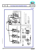
The diagrams on the following pages are principal
diagrams, and are MAN B&W's recommendation for
the design of external cooling water systems.
The systems are designed on the basis of the
following criteria:
1.
Simplicity.
2.
Separate HT temperature regulation for pro-
pulsion and alternator engines.
3.
HT temperature regulation on engine outlet.
4.
Preheating with surplus heat.
5.
Preheating in engine top, downwards.
6.
As few change-over valves as possible.
7.
Possibility for Holeby ICS-system.
Ad 1)
Cooling water systems have a tendency to be
unnecessarily complicated and thus uneconomic in
installation and operation. Therfore, we have attach-
ed great importance to simple diagram design with
optimal cooling of the engines and at the same time
installation- and operation- friendly systems result-
ing in economic advantages.
Ad 2)
Cooling of alternator engines should be inde-
pendent of the propulsion engine load and vice
versa. Therefore, there should be separate cooling
water temperature regulation thus ensuring optimal
running temperatures irrespective of load.
Ad 3)
The HT FW thermostatic valve should be
mounted on the engine's outlet side ensuring a
constant cooling water temperature above the en-
gine at all loads.
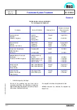
General
1613442-7.0
Page 1 (1)
If the thermostat valve is placed on the engine's inlet
side , which is not to be recommended, the tempera-
ture on the engine depends on the load with the risk
of overheating at full load.
Ad 4)
It has been stressed on the diagrams that the
alternator engines in stand-by position as well as the
propulsion engine in stop position are preheated,
optimally and simply, with surplus heat from the
running engines.
Ad 5)
If the engines are preheated with reverse
cooling water direction, i.e. from the top and down-
wards, an optimal heat distribution is reached in the
engine. This method is at the same time more
economic since the need for heating is less and the
water flow is reduced.
Ad 6)
The systems have been designed in such a
way that the change-over from sea operation to
harbour operation/stand-by with preheating can be
made with a minimum of manual or automatic inter-
ference.
Ad 7)
If the actual running situations demands that
one of the auxiliary engines should run on low-load,
the systems have been designed so that one of the
engines can be equipped with a cooling system for
ICS-operation(Integrated Charge air System).
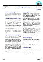
Fresh Water Treatment
The engine cooling water is, like fuel oil and lubricat-
ing oil, a medium which must be carefully selected,
treated, maintained and monitored.
Otherwise, corrosion, corrosion fatigue and cavita-
tion may occur on the surfaces of the cooling system
which are in contact with the water, and deposits
may form.
Corrosion and cavitation may reduce the life time
and safety factors of parts concerned, and deposits
will impair the heat transfer and may result in thermal
overload of the components to be cooled.
The treatment process of the cooling water has to be
effected before the first commission of the plant, i.e.
immediately after installation at the shipyard or at the
power plant.
Summary of Contents for L28/32H
Page 4: ......
Page 5: ...Introduction I 00...
Page 6: ......
Page 8: ......
Page 10: ......
Page 11: ...Designation of Cylinders In Line 98 19 1607568 0 1 Page 1 1 I 00 15 0...
Page 12: ......
Page 18: ......
Page 19: ...General information D 10...
Page 20: ......
Page 22: ......
Page 24: ......
Page 26: ......
Page 30: ......
Page 32: ......
Page 34: ......
Page 36: ......
Page 37: ...Basic Diesel Engine B 10...
Page 38: ......
Page 44: ......
Page 45: ...99 40 B 10 01 1 L28 32H Cross Section 1607528 5 2 Page 1 1...
Page 46: ......
Page 48: ......
Page 50: ......
Page 52: ......
Page 54: ......
Page 58: ......
Page 59: ...1607566 7 1 Page 1 1 Engine Rotation Clockwise B 10 11 1 General 98 18...
Page 60: ......
Page 61: ...Fuel Oil System B 11...
Page 62: ......
Page 68: ......
Page 72: ......
Page 74: ......
Page 76: ......
Page 79: ...Lubrication Oil System B 12...
Page 80: ......
Page 86: ......
Page 88: ......
Page 91: ...Cooling Water System B 13...
Page 92: ......
Page 98: ......
Page 106: ......
Page 108: ......
Page 112: ......
Page 113: ...Compressed Air System B 14...
Page 114: ......
Page 118: ......
Page 119: ...Combustion Air System B 15...
Page 120: ......
Page 124: ......
Page 126: ...Fig 1 Jet system 1639456 5 0 Page 2 2 Lambda Controller 93 44 L28 32H B 15 11 1...
Page 127: ...Exhaust Gas System B 16...
Page 128: ......
Page 136: ......
Page 140: ......
Page 142: ......
Page 144: ......
Page 146: ......
Page 147: ...Speed Control System B 17...
Page 148: ......
Page 150: ......
Page 152: ......
Page 153: ...Monitoring Equipment B 18...
Page 154: ......
Page 156: ......
Page 158: ......
Page 159: ...Safety and Control System B 19...
Page 160: ......
Page 164: ......
Page 166: ......
Page 177: ...Foundation B 20...
Page 178: ......
Page 180: ......
Page 183: ...Test running B 21...
Page 184: ......
Page 186: ......
Page 187: ...Spare Parts E 23...
Page 188: ......
Page 190: ......
Page 191: ...99 35 1607521 2 6 Page 1 1 Recommended Wearing Parts E 23 04 0 L28 32H...
Page 192: ......
Page 195: ...Tools P 24...
Page 196: ......
Page 200: ......
Page 202: ......
Page 203: ...Preservation and Packing B 25...
Page 204: ......
Page 206: ......
Page 208: ......
Page 210: ......
Page 211: ...Alternator G 50...
Page 212: ......
Page 216: ......
Page 218: ......

