91.32
General
1609535-5.1
Page 1 (2)
Exhaust Gas System
B 16 00 0
Internal exhaust gas system
From the exhaust valves, the gas is led to the
exhaust gas receiver where the fluctuating pressure
from the individual cylinders is equalized and the
total volume of gas led further on to the turbocharger,
at a constant pressure. After the turbocharger, the
gas is led to the exhaust pipe system.
The exhaust gas receiver is made of pipe sections,
one for each cylinder, connected to each other, by
means of compensators, to prevent excessive stress
in the pipes due to heat expansion.
In the cooled intermediate piece a thermometer for
reading the exhaust gas temperature is fitted and
there is also possibility of fitting a sensor for remote
reading.
To avoid excessive thermal loss and to ensure a
reasonably low surface temperature the exhaust
gas receiver is insulated.
External exhaust gas system
The exhaust back-pressure should be kept as low as
possible.
It is therefore of the utmost importance that the
exhaust piping is made as short as possible and with
few and soft bends.
Long, curved, and narrow exhaust pipes result in
higher back-pressure which may affect the engine
combustion.
The exhaust back-pressure should not exceed 250
mmWC at MCR. An exhaust gas velocity through the
pipe of maximum 35 m/sec is often suitable, but
depends on the actual piping.
Holeby will be pleased to assist in making a calcula-
tion of the exhaust back-pressure.
The gas outlet of turbocharger, the expansion bel-
lows, the exhaust pipe, and silencer, (in case of
silencer with spark arrestor care must be taken that
the cleaning parts are accessible), must be insula-
ted with a suitable material.
The insulation should be shielded by a thin plating,
and should comply with the requirements of the
classification society and/or the local authorities.
Exhaust pipe dimensions
It should be noted that concerning the maximum
exhaust gas velocity the pipe dimension after the
expansion bellow should be increased for some of
the engines.
The wall thickness of the external exhaust pipe
should be min. 3 mm.
Exhaust pipe mounting
When the exhaust piping is mounted, the radiation of
noise and heat must be taken into consideration.
Because of thermal fluctuations in the exhaust pipe,
it is necessary to use flexible as well as rigid
suspension points.
In order to compensate for thermal expansion in the
longitudinal direction, expansion bellows must be
inserted. The expansion bellows should preferably
be placed at the rigid suspension points.
Note: The exhaust pipe must not exert any force
against the gas outlet on the engine.
One sturdy fixed-point support must be provided for
the expansion bellows on the turbocharger. It should
be positioned, if possible, immediately above the
expansion bellow in order to prevent the transmis-
sion of forces, resulting from the weight, thermal
expansion or lateral displacement of the exhaust
piping, to the turbocharger.
The exhaust piping should be mounted with a slope
towards the gas outlet on the engine. It is recom-
mended to have drain facilities in order to be able to
remove condensate or rainwater.
Summary of Contents for L28/32H
Page 4: ......
Page 5: ...Introduction I 00...
Page 6: ......
Page 8: ......
Page 10: ......
Page 11: ...Designation of Cylinders In Line 98 19 1607568 0 1 Page 1 1 I 00 15 0...
Page 12: ......
Page 18: ......
Page 19: ...General information D 10...
Page 20: ......
Page 22: ......
Page 24: ......
Page 26: ......
Page 30: ......
Page 32: ......
Page 34: ......
Page 36: ......
Page 37: ...Basic Diesel Engine B 10...
Page 38: ......
Page 44: ......
Page 45: ...99 40 B 10 01 1 L28 32H Cross Section 1607528 5 2 Page 1 1...
Page 46: ......
Page 48: ......
Page 50: ......
Page 52: ......
Page 54: ......
Page 58: ......
Page 59: ...1607566 7 1 Page 1 1 Engine Rotation Clockwise B 10 11 1 General 98 18...
Page 60: ......
Page 61: ...Fuel Oil System B 11...
Page 62: ......
Page 68: ......
Page 72: ......
Page 74: ......
Page 76: ......
Page 79: ...Lubrication Oil System B 12...
Page 80: ......
Page 86: ......
Page 88: ......
Page 91: ...Cooling Water System B 13...
Page 92: ......
Page 98: ......
Page 106: ......
Page 108: ......
Page 112: ......
Page 113: ...Compressed Air System B 14...
Page 114: ......
Page 118: ......
Page 119: ...Combustion Air System B 15...
Page 120: ......
Page 124: ......
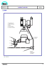
Page 126: ...Fig 1 Jet system 1639456 5 0 Page 2 2 Lambda Controller 93 44 L28 32H B 15 11 1...
Page 127: ...Exhaust Gas System B 16...
Page 128: ......
Page 136: ......
Page 140: ......
Page 142: ......
Page 144: ......
Page 146: ......
Page 147: ...Speed Control System B 17...
Page 148: ......
Page 150: ......
Page 152: ......
Page 153: ...Monitoring Equipment B 18...
Page 154: ......
Page 156: ......
Page 158: ......
Page 159: ...Safety and Control System B 19...
Page 160: ......
Page 164: ......
Page 166: ......
Page 177: ...Foundation B 20...
Page 178: ......
Page 180: ......
Page 183: ...Test running B 21...
Page 184: ......
Page 186: ......
Page 187: ...Spare Parts E 23...
Page 188: ......
Page 190: ......
Page 191: ...99 35 1607521 2 6 Page 1 1 Recommended Wearing Parts E 23 04 0 L28 32H...
Page 192: ......
Page 195: ...Tools P 24...
Page 196: ......
Page 200: ......
Page 202: ......
Page 203: ...Preservation and Packing B 25...
Page 204: ......
Page 206: ......
Page 208: ......
Page 210: ......
Page 211: ...Alternator G 50...
Page 212: ......
Page 216: ......
Page 218: ......

