08028-0D/H5250/94.08.12
General
98.20
B 16 01 1
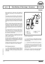
Water Washing of Turbocharger - Turbine
1607517-7.4
Page 1 (2)
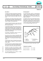
The tendency to fouling on the gas side of turbochar-
gers depends on the combustion conditions, which
are a result of the load on and the maintenance
condition of the engine as well as the quality of the
fuel oil used.
Fouling of the gas ways will cause higher exhaust
gas temperatures and higher surface temperatures
of the combustion chamber components and will
also lead to a lower performance.
Tests and practical experience have shown that
radial-flow turbines can be successfully cleaned by
injecting water into the inlet pipe of the turbine. The
cleaning effect is based on the water solubility of the
deposits and on the chemical action of the impinging
water droplets and the water flow rate.
The necessary water flow is dependent on the gas
flow and the gas temperature. Enough water must
be injected per time unit so that, not the entire flow
will evaporate, but about 0.25 l/min. will flow off
through the drainage opening in the gas outlet.
Ensuring that sufficient water has been injected.
Washing time : max. 10 min.
Service experience has shown that the above men-
tioned water flow gives the optimal cleaning effect. If
the water flow is reduced, the cleaning effect will be
reduced or dissappear. If the recommended water
flow is exceeded, there is a certain risk of an
accumulation of water in the turbine casing which
may result speed reduction of turbocharger.
The best cleaning effect is obtained by cleaning at
low engine load approx. 20% MCR. Cleaning at low
load will also reduce temperature shocks.
Experience has shown, that washing at regular
intervals is essential to successful cleaning, as exces-
sive fouling is thus avoided. Washing every week
during operation is therefore recommended.
The cleaning intervals can be shorter or longer
based on operational experience.
The water should be supplied from the fresh water
sanitary system and not from the fresh cooling wa-
ter system or sea water system. No cleaning agents
or solvents need to be added to the water. Water
consumption 1.5-5 l/min.
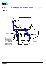
Water Washing System
The water washing system consists of a pipe system
equipped with a regulating valve, a valve, a 3-way
cock and a drain pipe with a ball valve from the gas
outlet.
The water for washing the turbine is supplied from
the external fresh water system through a flexible
hose with couplings. The flexible hose must be
disconnected after water washing.
By activating the valve and the regulating valve,
water is led through the 3-way cock to the exhaust
pipe intermediate flange which is equipped with a
channel to lead the water to the gas inlet of the
turbocharger.
The water which has not evaporated is led out
through the drain pipe in the gas outlet.
Summary of Contents for L28/32H
Page 4: ......
Page 5: ...Introduction I 00...
Page 6: ......
Page 8: ......
Page 10: ......
Page 11: ...Designation of Cylinders In Line 98 19 1607568 0 1 Page 1 1 I 00 15 0...
Page 12: ......
Page 18: ......
Page 19: ...General information D 10...
Page 20: ......
Page 22: ......
Page 24: ......
Page 26: ......
Page 30: ......
Page 32: ......
Page 34: ......
Page 36: ......
Page 37: ...Basic Diesel Engine B 10...
Page 38: ......
Page 44: ......
Page 45: ...99 40 B 10 01 1 L28 32H Cross Section 1607528 5 2 Page 1 1...
Page 46: ......
Page 48: ......
Page 50: ......
Page 52: ......
Page 54: ......
Page 58: ......
Page 59: ...1607566 7 1 Page 1 1 Engine Rotation Clockwise B 10 11 1 General 98 18...
Page 60: ......
Page 61: ...Fuel Oil System B 11...
Page 62: ......
Page 68: ......
Page 72: ......
Page 74: ......
Page 76: ......
Page 79: ...Lubrication Oil System B 12...
Page 80: ......
Page 86: ......
Page 88: ......
Page 91: ...Cooling Water System B 13...
Page 92: ......
Page 98: ......
Page 106: ......
Page 108: ......
Page 112: ......
Page 113: ...Compressed Air System B 14...
Page 114: ......
Page 118: ......
Page 119: ...Combustion Air System B 15...
Page 120: ......
Page 124: ......
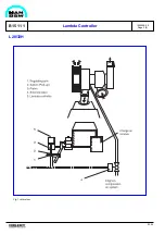
Page 126: ...Fig 1 Jet system 1639456 5 0 Page 2 2 Lambda Controller 93 44 L28 32H B 15 11 1...
Page 127: ...Exhaust Gas System B 16...
Page 128: ......
Page 136: ......
Page 140: ......
Page 142: ......
Page 144: ......
Page 146: ......
Page 147: ...Speed Control System B 17...
Page 148: ......
Page 150: ......
Page 152: ......
Page 153: ...Monitoring Equipment B 18...
Page 154: ......
Page 156: ......
Page 158: ......
Page 159: ...Safety and Control System B 19...
Page 160: ......
Page 164: ......
Page 166: ......
Page 177: ...Foundation B 20...
Page 178: ......
Page 180: ......
Page 183: ...Test running B 21...
Page 184: ......
Page 186: ......
Page 187: ...Spare Parts E 23...
Page 188: ......
Page 190: ......
Page 191: ...99 35 1607521 2 6 Page 1 1 Recommended Wearing Parts E 23 04 0 L28 32H...
Page 192: ......
Page 195: ...Tools P 24...
Page 196: ......
Page 200: ......
Page 202: ......
Page 203: ...Preservation and Packing B 25...
Page 204: ......
Page 206: ......
Page 208: ......
Page 210: ......
Page 211: ...Alternator G 50...
Page 212: ......
Page 216: ......
Page 218: ......

