08028-0D/H5250/94.08.12
Engine Control Box
E 19 06 6
General
Alarm and Safety System
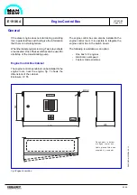
The engine control box is watching all alarm and
safety operating functions of the diesel engine.
In case of unintended conditions for the above
functions, the engine control box will initiate:
-
automatic stop of the engine (shutdown)
or
-
a warning indication (alarm)
In order to avoid an unintended re-starting after
release of a shutdown, there is a built-in reset
function which has to be activated before the engine
can be re-started. Remote reset is also possible.
Besides, there are built-in start/stop procedures for
the engine.
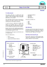
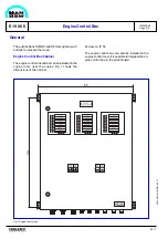
On the front cover of the engine control box there are
3 indication panels. One for the safety system and
two for the alarm system.
The engine control box will reflect the actual engine
automation/instrumentation. The items below are
general.
For the safety system there are indications for:
-
Power on
-
Engine run
-
Lub. oil shutdown
-
High temp. fresh water shutdown
-
Overspeed shutdown
-
Emergency shutdown
-
Start failure
-
Wire break
-
Start interlock (blocking)
-
Start interlock (local)
-
Starting air
For the alarm system there are indications for:
-
Lubricating oil inlet pressure
-
Prelubricating oil pressure
-
Fuel leakage
-
Oil level base frame *
-
lub. oil filter
-
Cooling water outlet temp.
94.17
-
Lub. oil inlet temp.
-
Cooling water press.
-
Tacho failure
-
Low supply voltage
-
High supply voltage
-
Alternator overheating
-
Lambda control failure
-
Fuse failure
-
Pre. lub pump failure
-
Overspeed
-
Spare x 4
Furthermore there are push buttons for:
-
Start of engine
-
Stop of engine
-
Reset
-
Lamp test
-
Diesel oil (MDO) mode with indication *
-
Heavy fuel oil (HFO) mode with indication *
* Options
Alarm Blocking
The engine control box is provided with a relay for
alarm blocking, so that alarm is avoided during
starting and stopping of the engine.
Start/Stop of the Diesel Engine
The diesel engine can be started and stopped by
means of push buttons on the panel. Furthermore, it
is possible to mount remote switches for these
functions.
If the diesel engine does not start during a starting
trial, a potential free switch will give the information
that there is a starting failure.
When the diesel engine is running, three relay
outputs are activated. One is used for start/stop of
the prelubricating pump, and one is used for start/
stop of the nozzle cooling pump.
Diesel Oil / Heavy Fuel Oil Mode
The valve control for MDO or HFO running mode is
incorporated in the engine control box.
It is possible to change the valve position on the
engine control box or remote.
1643403-4.0
Page 1 (2)
Summary of Contents for L28/32H
Page 4: ......
Page 5: ...Introduction I 00...
Page 6: ......
Page 8: ......
Page 10: ......
Page 11: ...Designation of Cylinders In Line 98 19 1607568 0 1 Page 1 1 I 00 15 0...
Page 12: ......
Page 18: ......
Page 19: ...General information D 10...
Page 20: ......
Page 22: ......
Page 24: ......
Page 26: ......
Page 30: ......
Page 32: ......
Page 34: ......
Page 36: ......
Page 37: ...Basic Diesel Engine B 10...
Page 38: ......
Page 44: ......
Page 45: ...99 40 B 10 01 1 L28 32H Cross Section 1607528 5 2 Page 1 1...
Page 46: ......
Page 48: ......
Page 50: ......
Page 52: ......
Page 54: ......
Page 58: ......
Page 59: ...1607566 7 1 Page 1 1 Engine Rotation Clockwise B 10 11 1 General 98 18...
Page 60: ......
Page 61: ...Fuel Oil System B 11...
Page 62: ......
Page 68: ......
Page 72: ......
Page 74: ......
Page 76: ......
Page 79: ...Lubrication Oil System B 12...
Page 80: ......
Page 86: ......
Page 88: ......
Page 91: ...Cooling Water System B 13...
Page 92: ......
Page 98: ......
Page 106: ......
Page 108: ......
Page 112: ......
Page 113: ...Compressed Air System B 14...
Page 114: ......
Page 118: ......
Page 119: ...Combustion Air System B 15...
Page 120: ......
Page 124: ......
Page 126: ...Fig 1 Jet system 1639456 5 0 Page 2 2 Lambda Controller 93 44 L28 32H B 15 11 1...
Page 127: ...Exhaust Gas System B 16...
Page 128: ......
Page 136: ......
Page 140: ......
Page 142: ......
Page 144: ......
Page 146: ......
Page 147: ...Speed Control System B 17...
Page 148: ......
Page 150: ......
Page 152: ......
Page 153: ...Monitoring Equipment B 18...
Page 154: ......
Page 156: ......
Page 158: ......
Page 159: ...Safety and Control System B 19...
Page 160: ......
Page 164: ......
Page 166: ......
Page 177: ...Foundation B 20...
Page 178: ......
Page 180: ......
Page 183: ...Test running B 21...
Page 184: ......
Page 186: ......
Page 187: ...Spare Parts E 23...
Page 188: ......
Page 190: ......
Page 191: ...99 35 1607521 2 6 Page 1 1 Recommended Wearing Parts E 23 04 0 L28 32H...
Page 192: ......
Page 195: ...Tools P 24...
Page 196: ......
Page 200: ......
Page 202: ......
Page 203: ...Preservation and Packing B 25...
Page 204: ......
Page 206: ......
Page 208: ......
Page 210: ......
Page 211: ...Alternator G 50...
Page 212: ......
Page 216: ......
Page 218: ......

