08028-0D/H5250/94.08.12
1631478-5.1
Page 1 (2)
High Temperature Preheater Control Box
E 19 13 0
General
01.10
Description
The preheater control box is for controlling the
electric heater built onto the engine for preheating of
the engines jacket cooling water during stand-still.
The control box consists of a cabinet with contactor
and control system. On the front of the cabinet there
is a lamp for "heater on" and a main switch for acti-
vating the system. Furthermore there is overload
protection for the heater element.
The temperature is controlled by means of an on/off
thermostat mounted in the common HT-outlet pipe.
Furthermore the system secures that the heater is
activated only when the engine is in stand-still.
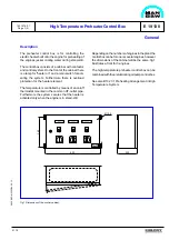
Depending on the numbers of engines in the plant, the
control box can be for one or several engines, however
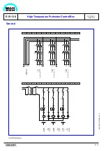
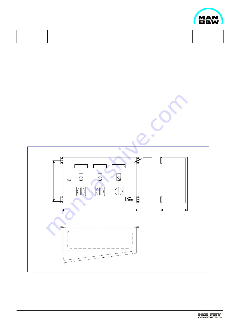
the dimensions of the cabinet will be the same. fig 1
illustrates a front for 3 engines.
The high temperature preheater control box can be
combined with the prelubricating oil pump control box.
See also B 13 23 1 Preheating Arrangement in High
Temperature System.
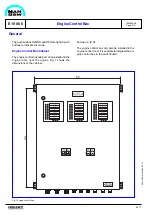
H.T. water preheater
Engine 2
H.T. water preheater
Engine 1
H.T. water preheater
Engine 3
340
630
Ø10.2
220
Heater
ON
Heater
ON
Heater
ON
Fig 1 Dimensions of the control cabinet.
Summary of Contents for L28/32H
Page 4: ......
Page 5: ...Introduction I 00...
Page 6: ......
Page 8: ......
Page 10: ......
Page 11: ...Designation of Cylinders In Line 98 19 1607568 0 1 Page 1 1 I 00 15 0...
Page 12: ......
Page 18: ......
Page 19: ...General information D 10...
Page 20: ......
Page 22: ......
Page 24: ......
Page 26: ......
Page 30: ......
Page 32: ......
Page 34: ......
Page 36: ......
Page 37: ...Basic Diesel Engine B 10...
Page 38: ......
Page 44: ......
Page 45: ...99 40 B 10 01 1 L28 32H Cross Section 1607528 5 2 Page 1 1...
Page 46: ......
Page 48: ......
Page 50: ......
Page 52: ......
Page 54: ......
Page 58: ......
Page 59: ...1607566 7 1 Page 1 1 Engine Rotation Clockwise B 10 11 1 General 98 18...
Page 60: ......
Page 61: ...Fuel Oil System B 11...
Page 62: ......
Page 68: ......
Page 72: ......
Page 74: ......
Page 76: ......
Page 79: ...Lubrication Oil System B 12...
Page 80: ......
Page 86: ......
Page 88: ......
Page 91: ...Cooling Water System B 13...
Page 92: ......
Page 98: ......
Page 106: ......
Page 108: ......
Page 112: ......
Page 113: ...Compressed Air System B 14...
Page 114: ......
Page 118: ......
Page 119: ...Combustion Air System B 15...
Page 120: ......
Page 124: ......
Page 126: ...Fig 1 Jet system 1639456 5 0 Page 2 2 Lambda Controller 93 44 L28 32H B 15 11 1...
Page 127: ...Exhaust Gas System B 16...
Page 128: ......
Page 136: ......
Page 140: ......
Page 142: ......
Page 144: ......
Page 146: ......
Page 147: ...Speed Control System B 17...
Page 148: ......
Page 150: ......
Page 152: ......
Page 153: ...Monitoring Equipment B 18...
Page 154: ......
Page 156: ......
Page 158: ......
Page 159: ...Safety and Control System B 19...
Page 160: ......
Page 164: ......
Page 166: ......
Page 177: ...Foundation B 20...
Page 178: ......
Page 180: ......
Page 183: ...Test running B 21...
Page 184: ......
Page 186: ......
Page 187: ...Spare Parts E 23...
Page 188: ......
Page 190: ......
Page 191: ...99 35 1607521 2 6 Page 1 1 Recommended Wearing Parts E 23 04 0 L28 32H...
Page 192: ......
Page 195: ...Tools P 24...
Page 196: ......
Page 200: ......
Page 202: ......
Page 203: ...Preservation and Packing B 25...
Page 204: ......
Page 206: ......
Page 208: ......
Page 210: ......
Page 211: ...Alternator G 50...
Page 212: ......
Page 216: ......
Page 218: ......

