B 10 01 1
General Description
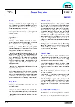
metal is welded on to the valve spindle seats.
The valve spindles are fitted with valve rotators
which turn the spindles a little each time the valves
open.
The cylinder head is equipped with replaceable seat
rings for inlet and exhaust valves.
The valve seat rings for inlet and exhaust valves are
identical.
The seat rings are made of heat-resistant steel,
hardened on the seating surface and water cooled in
order to assure low valve temperature and in-
creased overhaul intervals.
Valve Actuating Gear
The rocker arms are actuated through rollers, roller
guides and push rods. The roller guide for fuel pump
and for inlet and exhaust valves are mounted in one
common housing for each cylinder. This housing is
bolted to the engine frame.
Each rocker arm activates two spindles through a
spring-loaded valve bridge with thrust screws and
adjusting screws for valve clearance.
The valve actuating gear is pressure-feed lubricated
from the centralized lubricating system of the en-
gine. A non-return valve bloks the oil inlet to the
rocker arms during prelubricating.
Fuel Injection System
The engine is provided with one fuel injection pump,
an injection valve, and a high pressure pipe for each
cylinder.
The injection pump is mounted on the valve gear
housing by means of four screws. The pump con-
sists of a pump housing, a centrally placed pump
barrel and a plunger. The pump is activated by the
fuel cam, and the volume injected is controlled by
turning the plunger.
The fuel injection valve is located in a valve sleeve
in the center of the cylinder head. The opening of the
1605544-1.5
Page 2 (5)
L28/32H
96.12
valve is controlled by the fuel oil pressure, and the
valve is closed by a spring.
The high pressure pipe which is led through a bore
in the cylinder head is surrounded by a shielding
tube. The shielding tube has two holes in order to
ensure that any leakage will be drained off to the
cylinder head bore. The bore is equipped with drain
channel and pipe.
The complete injection equipment inclusive injection
pumps, high pressure and low pressure pipes is well
enclosed behind removable covers.
Piston
The piston, which is oil-cooled and of the monobloc
type made of nodular cast-iron, is equipped with 3
compression rings and 1 oil scraper ring.
By the use of compression rings with different barral-
shaped profiles and chrome-plated running sur-
faces, the piston ring pack is optimized for maximum
sealing effect and minimum wear rate.
The piston has a cooling oil space close to the piston
crown and the piston ring zone. The heat transfer
and thus the cooling effect is based on the shaker
effect arising during the piston movement. The cool-
ing medium is oil from the engine’s lubricating oil
system.
Oil is supplied to the cooling oil space through
channels from the oil grooves in the piston pin bos-
ses. Oil is drained from the cooling oil space through
ducts situated diametrically to the inlet channels.
The piston pin is fully floating and kept in position in
axial direction by two circlips (seeger rings). The
piston pin is equipped with channels and holes for
supply of oil to lubrication of the pin bosses and for
supply of cooling oil to the piston.
Connecting Rod
The connecting rod is die-forged. The big-end has an
inclined joint in order to facilitate the piston and
connecting rod assembly to be withdrawn up
Summary of Contents for L28/32H
Page 4: ......
Page 5: ...Introduction I 00...
Page 6: ......
Page 8: ......
Page 10: ......
Page 11: ...Designation of Cylinders In Line 98 19 1607568 0 1 Page 1 1 I 00 15 0...
Page 12: ......
Page 18: ......
Page 19: ...General information D 10...
Page 20: ......
Page 22: ......
Page 24: ......
Page 26: ......
Page 30: ......
Page 32: ......
Page 34: ......
Page 36: ......
Page 37: ...Basic Diesel Engine B 10...
Page 38: ......
Page 44: ......
Page 45: ...99 40 B 10 01 1 L28 32H Cross Section 1607528 5 2 Page 1 1...
Page 46: ......
Page 48: ......
Page 50: ......
Page 52: ......
Page 54: ......
Page 58: ......
Page 59: ...1607566 7 1 Page 1 1 Engine Rotation Clockwise B 10 11 1 General 98 18...
Page 60: ......
Page 61: ...Fuel Oil System B 11...
Page 62: ......
Page 68: ......
Page 72: ......
Page 74: ......
Page 76: ......
Page 79: ...Lubrication Oil System B 12...
Page 80: ......
Page 86: ......
Page 88: ......
Page 91: ...Cooling Water System B 13...
Page 92: ......
Page 98: ......
Page 106: ......
Page 108: ......
Page 112: ......
Page 113: ...Compressed Air System B 14...
Page 114: ......
Page 118: ......
Page 119: ...Combustion Air System B 15...
Page 120: ......
Page 124: ......
Page 126: ...Fig 1 Jet system 1639456 5 0 Page 2 2 Lambda Controller 93 44 L28 32H B 15 11 1...
Page 127: ...Exhaust Gas System B 16...
Page 128: ......
Page 136: ......
Page 140: ......
Page 142: ......
Page 144: ......
Page 146: ......
Page 147: ...Speed Control System B 17...
Page 148: ......
Page 150: ......
Page 152: ......
Page 153: ...Monitoring Equipment B 18...
Page 154: ......
Page 156: ......
Page 158: ......
Page 159: ...Safety and Control System B 19...
Page 160: ......
Page 164: ......
Page 166: ......
Page 177: ...Foundation B 20...
Page 178: ......
Page 180: ......
Page 183: ...Test running B 21...
Page 184: ......
Page 186: ......
Page 187: ...Spare Parts E 23...
Page 188: ......
Page 190: ......
Page 191: ...99 35 1607521 2 6 Page 1 1 Recommended Wearing Parts E 23 04 0 L28 32H...
Page 192: ......
Page 195: ...Tools P 24...
Page 196: ......
Page 200: ......
Page 202: ......
Page 203: ...Preservation and Packing B 25...
Page 204: ......
Page 206: ......
Page 208: ......
Page 210: ......
Page 211: ...Alternator G 50...
Page 212: ......
Page 216: ......
Page 218: ......

