08028-0D/H5250/94.08.12
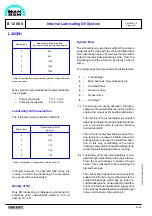
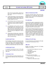
From the front main bearings channels are
bored in the crankshaft for lubricating of the
pump drive.
3)
The lubricating oil pipes, for the camshaft drive
gear wheels, are equipped with nozzles which
are adjusted to apply the oil at the points where
the gear wheels are in mesh.
4)
The lubricating oil pipe, and the gear wheels
for the governor drive are adjusted to apply the
oil at the points where the gear wheels are in
mesh.
5)
The lubricating oil to the rocker arms is led
through pipes to each cylinder head. It contin-
ues through bores in the cylinder head and
rocker arm to the movable parts to be lubri-
cated at rocker arms and valve bridge. Further,
lub. oil is led to the movable parts in need of
lubrication.
6)
Through a bore in the frame lub. oil is led to the
first camshaft bearing and through bores in the
camshaft from where it is distributed to the
other camshaft bearings.
Lubricating Oil Pump
The lubricating oil pump, which is of the gear wheel
type, is mounted on the front end of the engine and
is driven by means of the crankshaft through a
coupling. The oil pressure is controlled by an adjust-
able spring- loaded relief valve built-on the oil pump.
Lubricating Oil Cooler
As standard the lubricating oil cooler is of the plate
type. The cooler is mounted to the front end of the
base frame.
Thermostatic Valve
The thermostatic valve is a fully automatic three-way
valve with thermostatic elements set of fixed tempe-
rature.
1613544-6.4
Page 3 (4)
Internal Lubricating Oil System
B 12 00 0
L28/32H
99.48
Built-on Full-flow Depth Filter
The built-on lubricating oil filter is of the duplex paper
cartridge type. It is a depth filter with a norminel
fineness of 10-15 microns, and a safety filter with a
fineness of 60 microns.
Pre-lubricating
As standard the engine is equipped with an electric-
driven prelub. pump mounted parallel to the main
pump. The pump must be arranged for automatic
operation, ensuring stand-still of the prelubricating
pump when the engine is running, and running dur-
ing engine stand-still in stand-by position.
Running period of the prelubricating pump is prefer-
ably to be continuous. If intermittent running is requi-
red for energy saving purpose, the timing equipment
should be set for shortest possible intervals, say 2
minutes of running, 10 minures of stand-still, etc.
Further, it is recommended that the prelub. pump is
connected to the emergency switch board thus se-
curing that the engine is not started without
prelubrication.
Draining of the Oil Sump
It is recommended to use the separator suction pipe
for draining of the lubricating oil sump.
Optionals
Besides the standard components, the following
optionals can be built-on:
–
Level switch for low/high level in oil sump
(LAL/LAH 28)
–
Centrifugal by-pass filter
–
Hand wing pump
–
Filling plug
Pressure differential transmitting
–
PDT 21-22 Lub. oil inlet across filter
Temperature alarm high
–
TAH 20 Lub. oil inlet before cooler
Summary of Contents for L28/32H
Page 4: ......
Page 5: ...Introduction I 00...
Page 6: ......
Page 8: ......
Page 10: ......
Page 11: ...Designation of Cylinders In Line 98 19 1607568 0 1 Page 1 1 I 00 15 0...
Page 12: ......
Page 18: ......
Page 19: ...General information D 10...
Page 20: ......
Page 22: ......
Page 24: ......
Page 26: ......
Page 30: ......
Page 32: ......
Page 34: ......
Page 36: ......
Page 37: ...Basic Diesel Engine B 10...
Page 38: ......
Page 44: ......
Page 45: ...99 40 B 10 01 1 L28 32H Cross Section 1607528 5 2 Page 1 1...
Page 46: ......
Page 48: ......
Page 50: ......
Page 52: ......
Page 54: ......
Page 58: ......
Page 59: ...1607566 7 1 Page 1 1 Engine Rotation Clockwise B 10 11 1 General 98 18...
Page 60: ......
Page 61: ...Fuel Oil System B 11...
Page 62: ......
Page 68: ......
Page 72: ......
Page 74: ......
Page 76: ......
Page 79: ...Lubrication Oil System B 12...
Page 80: ......
Page 86: ......
Page 88: ......
Page 91: ...Cooling Water System B 13...
Page 92: ......
Page 98: ......
Page 106: ......
Page 108: ......
Page 112: ......
Page 113: ...Compressed Air System B 14...
Page 114: ......
Page 118: ......
Page 119: ...Combustion Air System B 15...
Page 120: ......
Page 124: ......
Page 126: ...Fig 1 Jet system 1639456 5 0 Page 2 2 Lambda Controller 93 44 L28 32H B 15 11 1...
Page 127: ...Exhaust Gas System B 16...
Page 128: ......
Page 136: ......
Page 140: ......
Page 142: ......
Page 144: ......
Page 146: ......
Page 147: ...Speed Control System B 17...
Page 148: ......
Page 150: ......
Page 152: ......
Page 153: ...Monitoring Equipment B 18...
Page 154: ......
Page 156: ......
Page 158: ......
Page 159: ...Safety and Control System B 19...
Page 160: ......
Page 164: ......
Page 166: ......
Page 177: ...Foundation B 20...
Page 178: ......
Page 180: ......
Page 183: ...Test running B 21...
Page 184: ......
Page 186: ......
Page 187: ...Spare Parts E 23...
Page 188: ......
Page 190: ......
Page 191: ...99 35 1607521 2 6 Page 1 1 Recommended Wearing Parts E 23 04 0 L28 32H...
Page 192: ......
Page 195: ...Tools P 24...
Page 196: ......
Page 200: ......
Page 202: ......
Page 203: ...Preservation and Packing B 25...
Page 204: ......
Page 206: ......
Page 208: ......
Page 210: ......
Page 211: ...Alternator G 50...
Page 212: ......
Page 216: ......
Page 218: ......

