08028-0D/H5250/94.08.12
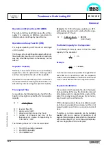
Operation on Marine Diesel Oil (MDO)
The built-on full-flow depth filter cleans the oil thor-
oughly. For operation on MDO we recommend to
install a built-on centrifugal by-pass filter too.
Operation on Heavy Fuel Oil (HFO)
For engines operating on HFO a lub. oil centrifugal
unit is required.
Continuous lub. oil centrifugation plus a built-on full-
flow depth filter clean the oil in a sufficient and safe
way. Any other filter system is not necessary, but not
wasted.
Separator Capacity
Normally, it is recommended to use a self-cleaning
separator in order to optimize the cleaning period
and thus also optimize the size of the separator.
Separators for manual cleaning can be used when
the reduced effective cleaning time is taken into con-
sideration by dimensioning the separator capacity.
The required Flow
As a guidance, the following formula should form the
basis for choosing the required flow for the separator
capacity:
Q
=
P x 1.36 x n
t
Q = required flow (l/h)
P = engine output (kW).
t
= actual operating time per day (hour)
n = number of turnovers per day of the
theoretical oil volume corresponding to
1.36 l/kW or 1 l/HP.
The following values for "n" are recommended:
n = 5 for HFO operating (residual)
n = 4 for MDO operating
n = 3 for distillate fuel
1643494-3.3
Page 1 (2)
Treatment of Lubricating Oil
B 12 15 0
General
98.33
Example: for 1000 kW engine operating on HFO,
self-cleaning separator with a daily effective sepa-
rating period of 23 hours:
Q
=
1000 x 1.36 x 5
= 295 l/h
23
(0.30 l/h kW)
The Rated Capacity for the Separator
The following formula is used to find the rated
capacity for the separator:
Q
=
l/h
0.2
Example:
295
=
1478 l/h
0.2
0.2 is the recommended separator throughput factor
and shall be in accordance with the separator
maker's recommendations. This factor can be found
in the manual delivered from the separator maker.
Separator Installation
It is recommended to separate the oil on the engine
while operating. In this way, the dirt can be removed
immediately when it is supplied to the engine. At the
same time energy is saved because it is not neces-
sary to warm up the oil that much.
With multi-engine plants the best installation would
be to have one separator per engine, but this is not
always realistic seen from an economical point of
view.
Therefore, a common separator can be installed,
possibly with one in reserve for operation of all
engines through a pipe system, which can be carried
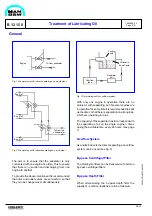
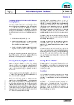
out in various ways. Fig. 1 and 2 show a principle lay-
out for a single plant and a multi-plant.
Summary of Contents for L28/32H
Page 4: ......
Page 5: ...Introduction I 00...
Page 6: ......
Page 8: ......
Page 10: ......
Page 11: ...Designation of Cylinders In Line 98 19 1607568 0 1 Page 1 1 I 00 15 0...
Page 12: ......
Page 18: ......
Page 19: ...General information D 10...
Page 20: ......
Page 22: ......
Page 24: ......
Page 26: ......
Page 30: ......
Page 32: ......
Page 34: ......
Page 36: ......
Page 37: ...Basic Diesel Engine B 10...
Page 38: ......
Page 44: ......
Page 45: ...99 40 B 10 01 1 L28 32H Cross Section 1607528 5 2 Page 1 1...
Page 46: ......
Page 48: ......
Page 50: ......
Page 52: ......
Page 54: ......
Page 58: ......
Page 59: ...1607566 7 1 Page 1 1 Engine Rotation Clockwise B 10 11 1 General 98 18...
Page 60: ......
Page 61: ...Fuel Oil System B 11...
Page 62: ......
Page 68: ......
Page 72: ......
Page 74: ......
Page 76: ......
Page 79: ...Lubrication Oil System B 12...
Page 80: ......
Page 86: ......
Page 88: ......
Page 91: ...Cooling Water System B 13...
Page 92: ......
Page 98: ......
Page 106: ......
Page 108: ......
Page 112: ......
Page 113: ...Compressed Air System B 14...
Page 114: ......
Page 118: ......
Page 119: ...Combustion Air System B 15...
Page 120: ......
Page 124: ......
Page 126: ...Fig 1 Jet system 1639456 5 0 Page 2 2 Lambda Controller 93 44 L28 32H B 15 11 1...
Page 127: ...Exhaust Gas System B 16...
Page 128: ......
Page 136: ......
Page 140: ......
Page 142: ......
Page 144: ......
Page 146: ......
Page 147: ...Speed Control System B 17...
Page 148: ......
Page 150: ......
Page 152: ......
Page 153: ...Monitoring Equipment B 18...
Page 154: ......
Page 156: ......
Page 158: ......
Page 159: ...Safety and Control System B 19...
Page 160: ......
Page 164: ......
Page 166: ......
Page 177: ...Foundation B 20...
Page 178: ......
Page 180: ......
Page 183: ...Test running B 21...
Page 184: ......
Page 186: ......
Page 187: ...Spare Parts E 23...
Page 188: ......
Page 190: ......
Page 191: ...99 35 1607521 2 6 Page 1 1 Recommended Wearing Parts E 23 04 0 L28 32H...
Page 192: ......
Page 195: ...Tools P 24...
Page 196: ......
Page 200: ......
Page 202: ......
Page 203: ...Preservation and Packing B 25...
Page 204: ......
Page 206: ......
Page 208: ......
Page 210: ......
Page 211: ...Alternator G 50...
Page 212: ......
Page 216: ......
Page 218: ......

