MAN B&W
6.04
Page 5 of 12
MAN Diesel
MAN B&W S50MC/MC-C-TII, S46MC-C-TII, S42MC-TII,
S40MC-C-TII, S35MC/MC-C-TII, L35MC-TII, S26MC-TII
198 71 42-2.0
Freshwater Generator
If a freshwater generator is installed and is utilis-
ing the heat in the jacket water cooling system,
it should be noted that the actual available heat
in the jacket cooling water system is
lower than
indicated by the heat dissipation figures valid for
nominal MCR (L
1
) given in the List of Capacities.
This is because the latter figures are used for
dimensioning the jacket water cooler and hence
incorporate a safety margin which can be needed
when the engine is operating under conditions
such as, e.g. overload. Normally, this margin is
10% at nominal MCR.
Calculation Method
For a derated diesel engine, i.e. an engine having
a specified MCR (M) equal to optimising point (O)
different from L
1
, the relative jacket water heat dis-
sipation for point M and O may be found, as previ-
ously described, by means of Fig. 6.04.02.
At part load operation, lower than optimising
power, the actual jacket water heat dissipation will
be reduced according to the curves for fixed pitch
propeller (FPP) or for constant speed, controllable
pitch propeller (CPP), respectively, in Fig. 6.04.04.
With reference to the above, the heat actually
available for a derated diesel engine may then be
found as follows:
1.
Engine power equal to specified MCR
power M (equal to optimising point O).
For specified MCR (M) = optimising power
(O), the diagram Fig. 6.04.02 is to be used,
i.e. giving the percentage correction factor
‘Q
jw%
’ and hence for optimising power P
O
:
Q
jw,O
= Q
jw,L1
x
Q
jw%
___
100
x 0.9 (0.88)
[1]
2.
Engine power lower than optimising power.
For powers lower than the optimising power,
the value Q
jw,O
found for point O by means of
the above equation [1] is to be multiplied by
the correction factor k
p
found in Fig. 6.04.04
and hence
Q
jw
= Q
jw,O
x k
p
15%/0%
[2]
where
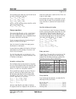
Part load correction factor for jacket
cooling water heat dissipation
Engine load, % of optimising power (O)
FPP : Fixed pitch propeller
CPP : Controllable pitch propeller, constant speed
k
p
1.0
0.9
0.8
0.7
0.6
0.5
0.4
0.3
0.2
0.1
0
0
10
20
30
40
50
60
70
80
90
100%
FPP
CPP
178 59 45-7.0
Fig. 6.04.04: Correction factor ‘kp’ for jacket cooling
water heat dissipation at part load, relative to heat dis-
sipation at optimising power
FPP : k
p
= 0.742 x
P
S
__
P
O
+ 0.258
CPP : k
p
= 0.822 x
P
S
__
P
O
+ 0.178
Q
jw
= jacket water heat dissipation
Q
jw,L1
= jacket water heat dissipation at nominal
MCR (L
1
)
Q
jw%
= percentage correction factor from
Fig. 6.04.02
Q
jw,O
= jacket water heat dissipation at optimising
power (O), found by means of equation [1]
k
p
= part load correction factor from Fig. 6.04.04
0.9 = factor for safety margin of cooler, tropical
ambient conditions
The heat dissipation is assumed to be more or less
independent of the ambient temperature conditions,
yet the safety margin/ambient condition factor of
about 0.88 instead of 0.90 will be more accurate for
ambient conditions corresponding to ISO tempera-
tures or lower. The heat dissipation tolerance from
15% to 0% stated above is based on experience.
Summary of Contents for B&W L35MC6-TII
Page 4: ......
Page 10: ......
Page 18: ......
Page 19: ...MAN B W MAN Diesel Engine Design 1 ...
Page 20: ......
Page 35: ...MAN B W MAN Diesel Engine Layout and Load Diagrams SFOC 2 ...
Page 36: ......
Page 52: ......
Page 64: ......
Page 65: ...MAN B W MAN Diesel Turbocharger Selection Exhaust Gas By pass 3 ...
Page 66: ......
Page 72: ......
Page 73: ...MAN B W MAN Diesel Electricity Production 4 ...
Page 74: ......
Page 95: ...MAN B W MAN Diesel Installation Aspects 5 ...
Page 96: ......
Page 132: ......
Page 146: ......
Page 147: ...MAN B W MAN Diesel List of Capacities Pumps Coolers Exhaust Gas 6 ...
Page 148: ......
Page 171: ...MAN B W MAN Diesel Fuel 7 ...
Page 172: ......
Page 186: ......
Page 187: ...MAN B W MAN Diesel Lubricating Oil 8 ...
Page 188: ......
Page 203: ...MAN B W MAN Diesel Cylinder Lubrication 9 ...
Page 204: ......
Page 213: ...MAN B W MAN Diesel Piston Rod Stuffing Box Drain Oil 10 ...
Page 214: ......
Page 215: ......
Page 217: ...MAN B W MAN Diesel Central Cooling Water System 11 ...
Page 218: ......
Page 223: ...MAN B W MAN Diesel Seawater Cooling System 12 ...
Page 224: ......
Page 234: ......
Page 235: ...MAN B W MAN Diesel Starting and Control Air 13 ...
Page 236: ......
Page 242: ......
Page 243: ...MAN B W MAN Diesel Scavenge Air 14 ...
Page 244: ......
Page 256: ......
Page 257: ...MAN B W MAN Diesel Exhaust Gas 15 ...
Page 258: ......
Page 272: ......
Page 273: ...MAN B W MAN Diesel Engine Control System 16 ...
Page 274: ......
Page 289: ...MAN B W MAN Diesel Vibration Aspects 17 ...
Page 290: ......
Page 304: ......
Page 305: ...MAN B W MAN Diesel Monitoring Systems and Instrumentation 18 ...
Page 306: ......
Page 328: ......
Page 329: ...MAN B W MAN Diesel Dispatch Pattern Testing Spares and Tools 19 ...
Page 330: ......
Page 360: ......
Page 361: ...MAN B W MAN Diesel Project Suppport and Documentation 20 ...
Page 362: ......
Page 371: ...MAN B W MAN Diesel Appendix A ...
Page 372: ......

