MAN B&W
9.02
Page 1 of 5
MAN Diesel
MAN B&W K98MC6/7, K98MCC6/7, S90MC-C7/8, K90MC-C6,
S80MC6, S80MC-C7/8, K80MC-C6, S70MC6, S/L70MC-C7/8,
S60MC6, S/L60MC-C7/8, S50MC6, S50MC-C7/8, S46MC-C7/8,
S42MC7, S40MC-C9, S35MC-C9, L35MC6, S26MC6
198 56 32-4.2
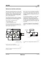
MAN B&W Alpha Cylinder Lubrication System
The MAN B&W Alpha cylinder lubrication system,
see Figs. 9.02.02 and 9.02.03, is designed to sup-
ply cylinder oil intermittently, every 2 to 20 engine
revolutions with electronically controlled timing
and dosage at a defined position.
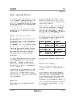
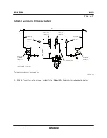
Cylinder lubricating oil is fed to the engine by
means of a pump station which as standard is
mounted on the engine, EoD: 4 42 150, or could
be placed in the engine room, option: 4 42 152.
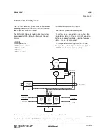
The pump station has two pumps (one operating,
the other stand-by with automatic start up) with
in-line filters and a heater, see Fig. 9.02.02.
The oil fed to the injectors is pressurised by
means of one or two Alpha Lubricators placed
on each cylinder and equipped with small
multipiston pumps, see Fig. 9.02.03.
Accumulator tanks on the lubricator inlet pipes
ensure adequate filling of the lubricator while ac-
cumulators on the outlet pipes serve to dampen
the pressure fluctuations. The oil pipes fitted on
the engine is shown in Fig. 9.02.03.
On engines with double lubricators, a by-pass
valve allows for circulating and heating the cyl-
inder oil before starting the engine under cold
engine room conditions. On engines with one lu-
bricator per cylinder, this is done by means of the
valve on the cylinderblock intended for emptying
the accumulator.
Prior to start-up, the cylinders can be pre-lubricat-
ed and, during the runningin period, the operator
can choose to increase the lubricating oil feed
rate to a max. setting of 200%.
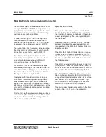
System control units
The cylinder lubrication system is controlled by
the Master Control Unit (MCU) which calculates
the injection frequency on the basis of the engine-
speed signal given by the tacho signal (ZE) and
the fuel index.
Lubricating control functions such as ‘mep de-
pendent’ and ‘load change dependent’ are all
incorporated in the MAN B&W Alpha cylinder lu-
brication system.
The MAN B&W Alpha Cylinder Lubricator is pre-
ferably to be controlled in accordance with the
Alpha Adaptive Cylinder oil Control (Alpha ACC)
feed rate system. The Alpha ACC is explained in
the following page.
The MCU is equipped with a Backup Control Unit
(BCU) which, if the MCU malfunctions, activates
an alarm and takes control automatically or manu-
ally, via a Switch Board Unit (SBU), Fig. 9.02.04.
The MCU, BCU and SBU together comprise the
Alpha Cylinder Lubricator Control Unit (ALCU) in
shape of a single steel cabinet which is, as stand-
ard, located in the Engine Control Room. Fig.
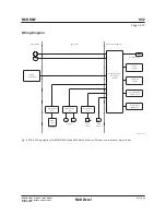
9.02.05 shows the wiring diagram for the MAN
B&W Alpha Cylinder Lubrication System.
The yard supply should be according to the items
shown in Fig. 9.02.02 within the broken line.
Summary of Contents for B&W L35MC6-TII
Page 4: ......
Page 10: ......
Page 18: ......
Page 19: ...MAN B W MAN Diesel Engine Design 1 ...
Page 20: ......
Page 35: ...MAN B W MAN Diesel Engine Layout and Load Diagrams SFOC 2 ...
Page 36: ......
Page 52: ......
Page 64: ......
Page 65: ...MAN B W MAN Diesel Turbocharger Selection Exhaust Gas By pass 3 ...
Page 66: ......
Page 72: ......
Page 73: ...MAN B W MAN Diesel Electricity Production 4 ...
Page 74: ......
Page 95: ...MAN B W MAN Diesel Installation Aspects 5 ...
Page 96: ......
Page 132: ......
Page 146: ......
Page 147: ...MAN B W MAN Diesel List of Capacities Pumps Coolers Exhaust Gas 6 ...
Page 148: ......
Page 171: ...MAN B W MAN Diesel Fuel 7 ...
Page 172: ......
Page 186: ......
Page 187: ...MAN B W MAN Diesel Lubricating Oil 8 ...
Page 188: ......
Page 203: ...MAN B W MAN Diesel Cylinder Lubrication 9 ...
Page 204: ......
Page 213: ...MAN B W MAN Diesel Piston Rod Stuffing Box Drain Oil 10 ...
Page 214: ......
Page 215: ......
Page 217: ...MAN B W MAN Diesel Central Cooling Water System 11 ...
Page 218: ......
Page 223: ...MAN B W MAN Diesel Seawater Cooling System 12 ...
Page 224: ......
Page 234: ......
Page 235: ...MAN B W MAN Diesel Starting and Control Air 13 ...
Page 236: ......
Page 242: ......
Page 243: ...MAN B W MAN Diesel Scavenge Air 14 ...
Page 244: ......
Page 256: ......
Page 257: ...MAN B W MAN Diesel Exhaust Gas 15 ...
Page 258: ......
Page 272: ......
Page 273: ...MAN B W MAN Diesel Engine Control System 16 ...
Page 274: ......
Page 289: ...MAN B W MAN Diesel Vibration Aspects 17 ...
Page 290: ......
Page 304: ......
Page 305: ...MAN B W MAN Diesel Monitoring Systems and Instrumentation 18 ...
Page 306: ......
Page 328: ......
Page 329: ...MAN B W MAN Diesel Dispatch Pattern Testing Spares and Tools 19 ...
Page 330: ......
Page 360: ......
Page 361: ...MAN B W MAN Diesel Project Suppport and Documentation 20 ...
Page 362: ......
Page 371: ...MAN B W MAN Diesel Appendix A ...
Page 372: ......


